
Abstract
This chapter is divided into three main parts: (1) fundamental principles of materials handling, (2) a wide selection of material handling equipment classified as conveyors, trucks, cranes, and hoists, and (3) material handling system design. Each type of equipment is graphically illustrated, and accompanied by relevant remarks concerning purchase cost, maintenance cost, frequency of use load moving distance, and volume of material. Additionally, typical material handling accessories, such as boxes, tote pans, pallets, and skids are described. The combination of principles and guidelines on equipment selection provide a basis for designing, analyzing, and improvement material handling systems. A main component of the chapter is the development and computerization of a decision-support tool for material handling equipment selection. Material handling requirements and costs are also discussed. Section III of the factory design project is illustrated using the selected product.
Keywords
- Material handling principles
- Material handling equipment (MHE)
- Conveyors
- Hoists
- Cranes
- Trucks
- Accessories
- MHE decision-support methodology
- Material handling costs

7.1 Introduction
From an engineering point of view, materials handling is defined as the art and science involved in the moving, packaging, and storing of substances in any form. A materials handling system is defined as a series of related equipment elements or devices designed to work in concert or in sequence to accomplish the movement, storage, and control of materials in an operating environment and with designated materials. This chapter addresses the important concepts of materials handling, equipment, and systems design. The drawings below the chapter title illustrate the range of possible material handling equipment encountered in factory design. The next chapter addresses some of the details of material handling system design and analysis and their integration with the layout through quantitative techniques. Of key importance at this point in the factory project is to conjoin the layout and the material handling system. According to the Material Handling Institute (MHI),
material handling embraces all of the basic operations involved in the movement of bulk, packaged, and individual products in a semisolid or solid state by means of machinery, and within the limits of a place of business.
First, material handling involves the movement of material in a horizontal (transfer) and vertical (lifting) direction, as well as the loading and unloading of items. Second, materials moved include raw material to workstations, semifinished products between workstations, and finished products to their storage locations. Third, the selection of equipment is an important activity of designing a material handling system. Fourth, the term “bulk” indicates that materials are moved in large, unpacked volumes (such as sand, sawdust, and coal). Fifth, using machinery for handling material is the preferred method, although the investment might be high. The objectives of material handling may be summarized as follows [10]:
-
1.
Increase efficiency of material flow
-
2.
Reduce material handling cost
-
3.
Improve facility utilization
-
4.
Improve safety and working conditions
-
5.
Facilitate the manufacturing process
-
6.
Increase productivity
Material handling can account for 30–75% of production costs and can reduce operational costs by 15–30%. It affects building requirements, departmental arrangements, and production time. We shall discuss the various equipment types and their functions in subsequent sections of this chapter. A very general reference is the Materials Handling Handbook [8].
This chapter has three major parts:
-
1.
Fundamental principles of materials handling
-
2.
Material handling equipment selection
-
3.
Material handling system design
We discuss the fundamental scope of the chapter and basic definitions in Sect. 7.2, the principles of material handling in Sect. 7.3, an outline of the procedure for conducting material handling system design in Sect. 7.4, the equipment used in material handling in Sect. 7.5, a decision-support tool for material handling equipment selection in Sect. 7.6, the corresponding computerized program in Sect. 7.7, material handling requirements and costs in Sect. 7.8, and Section III of the factory design project in Sect. 7.9. Finally, Sect. 7.10 summarizes and concludes the chapter.
In Chap. 8 detailed design tools and techniques are described for material handling system design, such as is available with open queuing networks, conveyor design and analysis, closed queuing network models for transfer lines, and discrete-event simulation tools for cellular network design and layout.
7.2 Scope and Definitions
There is a very strong correlation between the design of facilities and the design of the material handling system (MHS). In fact, it is fundamentally a symbiotic relationship. Certain facilities are probably best configured once one knows and understands the material handling system, while for others, the MHS can be determined only after the facility layout design is well established. In the best of all worlds, the design of the MHS and the facility layout should be done simultaneously. This is a demanding task, but one which should be seriously considered.
Examining the sample manufacturing plant layout in Fig. 7.1, one sees that there is a spatial/hierarchical relationship involving the vehicles and equipment required in the MHS design.
-
Level 1: Certain MHS equipment will bring in raw materials and deliver finished goods to and from the boundary of the facility. (Normally the spatial area over which the MHS equipment works here is very expansive.)
-
Level 2: Other MHS equipment will move raw materials and completed parts and subassemblies between departments. (Normally the area of extent is much smaller.)
-
Level 3: Other MHS equipment will be utilized to move parts and components between the specified workstations and individual machines. (Here, point-to-point movement within a fairly restricted area is needed.)

Manufacturing floor layout with hierarchical MHS levels
Semitrailer trucks, railcars, forklifts, conveyors, dollies, hand trucks, and people movement all must work together in a coordinated systemwide effort. Thus, within this particular factory design there are at least three levels of movement. This is typical in a manufacturing layout problem. There must be some way to coordinate the movements of the MHS equipment between the levels in the facility, if it is to function effectively. These hierarchical levels relate directly to the queuing network model to be discussed in Chap. 8, which is based on nested types of material handling transfers.
7.3 Principles of Material Handling
As noted in Chap. 1, a principle is a general rule, fundamental concept, or statement of an observable fact. In the field of material handling, various principles can be invoked to analyze, plan, and manage material handling systems.
In 1968, the College–Industry Committee for Material Handling Education (CIC-MHE) [2] published a preliminary set of principles, which since then have undergone a sequence of reorganizations and redefinitions, based on additional knowledge generated by practitioners in the field. In essence, the material handling systems can be considered as general guidelines that can be used to compare and evaluate material handling systems. Figure 7.2 lists the 10 most important principles used today in the field. These principles impact the flow, cost, space utilization, safety, process and yield (productivity) of a manufacturing operation.

Material handling principles
-
1.
Planning Principle: A material handling facility should be the result of a cohesive and structured unit of specific courses of action (i.e., a plan) to determine what material needs to be moved, when and where it will be moved, and how it will be done.
-
2.
Standardization Principle: Methods, equipment, control devices, and software should be standardized without reducing the level of performance and the need for flexibility.
-
3.
Work Principle: Material handling flow should be as low as possible within the requirements demanded by the effectiveness and efficiency of a material handling system. “The best flow is no flow.”
-
4.
Ergonomic Principle: Material handling activities should be designed and proper equipment chosen after taking into consideration human capabilities and limitations to enhance the level of safety and working conditions.
-
5.
Unit Load Principle: The amount of material to be moved or stored as a unit should be sized and configured according to the specific needs and objectives of the material handling facility.
-
6.
Space Utilization Principle: The cubic space should be used as effectively and efficiently as possible.
-
7.
System Principle: A material handling system consists of a collection of elements working and interacting together as a unit to perform a common function. Alternatively, material handling activities and facilities are integrated to form a coordinated operational system including receiving, inspection, storage, production, assembly, packaging, load unitizing, order selection, shipping, transportation, and returns handling.
-
8.
Automation Principle: The level of mechanization and automation depends on the specific operational requirements and financial capabilities of each situation.
-
9.
Environmental Principle: Environmental impact and energy consumption should be important factors in the selection of a material handling system.
-
10.
Life Cycle Cost Principle: In the economic analysis of a material handling system all cash flows need to be considered along the service life of the system.
7.3.1 Unit Load Principle
The standardization principle is an important notion in material handling. Often it influences the application of the unit load principle. Basically, the larger the unit load handled, the smaller the cost per unit handled [2]. A unit load is defined as an individual item, multiple items, or a mass of bulk material too large for manual handling, that can be picked up and moved as a single object and, once released, will retain its initial arrangement for subsequent moves [2]. Most unit loads are handled by some type of pallet or skid.
Once the unit load is defined for a manufacturing facility, it will begin to dictate the type, size, and configuration of material handling equipment needed. While the unit load has many advantages, it has some disadvantages related to the cost of unitizing and deunitizing, equipment and space requirements, the problem of returning empty pallets and skids, and the lack of equipment on either or both ends of the move [2]. It can be a difficult problem to define the unit load in practice.
For the factory project the selection of a unit load may be rather straightforward, since normally the parts moving in the factory will not be very large and will be moved in some cases manually, so that no significant material handling problems are anticipated.
7.4 Designing Material Handling Systems
Designing the material handling system (MHS) for a facility is a major undertaking. This section provides a brief overview of the process of material handling systems (MHS) design as it relates especially to the factory project. Section 7.6 provides a detailed guide for the design and selection of material handling equipment. This guide is closely related to the factory design project.
The activity areas within the plant are not static entities, because they always contain dynamically moving parts, people, or equipment. Within a department of the plant, there usually is a collection of machines with (1) an entry point, (2) a staging area, (3) processing, (4) finishing, (5) shipping, and (6) exit points. The sequence of materials flow is fairly typical of most manufacturing plants, and most facilities in general have prespecified sequences of operations within.
Figure 7.3 illustrates a typical department with its subactivities. In general, each department maintains a well-defined hierarchy of activities with a number of subareas or activities wherein the flow of materials is channeled. The nodes in the diagram represent activities and the arrows represent potential MHS moves. Possible equipment and manual moves are indicated on the diagram. Often certain conveying or transportation equipment is needed in order to move the parts, subassemblies, and finished goods according to this predefined sequence of operations through the department. Thus, the entire plant can be conceived as a hierarchical collection of departments with subactivities and an associated MHS for transferring the parts, people, and equipment between them. The main issue is, how to identify, organize, and structure this hierarchical system of activities into one overall functional system. This is a crucial design issue in facility planning. In Chap. 8, we describe a queuing network planning tool to design and analyze this hierarchical MHS system design.

Hierarchical department representation
Also, in the factory project stages, once the route sheets and standard times are completed and the quantities of material, equipment, and personnel are determined, one should develop the layout planning sheets which describe the fundamental relationship between the facility layout and the MHS. These layout planning sheets provide one of the detailed inputs for the MHS system design process. See Chap. 4 for an example of a typical layout planning sheet and Sect. 7.7 for the integration of all sheets in the factory project (Section III).
7.5 Material Handling Equipment
We now provide a brief description of the types of material handling equipment often encountered in a factory project, as listed in Fig. 7.4. The figure shows a layout with specified locations for typical material handling equipment. The figure illustrates the point that industrial trucks have wide-area access to the entire plant, cranes and hoists have a limited area extent, and conveyors have point-to-point accessibility.

Diagram of key material handling equipment and factory plan [5]
Most material handling equipment can be characterized using the following classification system:
-
Input Load: The product or item can normally be considered as a unit load (U) or a bulk (batch) load (B).
-
Transfer Mechanism: The location of the MHS equipment can either be on top of the ground or floor (T), overhead (O), or embedded in the floor (I).
-
Output of Load: The type of queuing system for which the MHS equipment deposits the load can either be accumulating (A) or non-accumulating (N). Accumulating refers to the fact that the load will queue up on the device or at a workstation. Non-accumulating can be thought of as no queue at all, since when the material handling equipment stops, the load is dispatched individually, with no queue forming along the material handling equipment.
Figure 7.5 illustrates the range of equipment involved in MHS design. Section 7.6 provides a detailed description of the decision-support tool that is included in the textbook to help the students choose the most appropriate type of material handling device for their factory layout project. The descriptions provided below offer an overview and introduction of the type and range of material handling devices included in the decision-support tool but are not meant to be an exhaustive description. We shall highlight certain pieces of equipment that commonly occur in factory layouts, providing a sketch, a brief description, and a summary evaluation of the equipment according to the following criteria: initial cost, maintenance cost, frequency of use, load distance moved, and volume of material moved.

MHS icons
7.5.1 Conveyors
Conveyors are typically used for point-to-point and department-to-department movement, assembly operations, and for integrating production departments with automated storage and retrieval systems along fixed paths. As indicated by Konz [6], the American Material Handling Society lists 57 types of conveyors. Conveyors move materials continuously over a fixed path. There must be a sufficient flow volume between the connection points of the conveyor in order to justify its use. Conveyors are best used for high-volume items for a fairly constant flow along a fixed route. Most conveyor systems are tailored to fit the specific manufacturing and warehousing function they are intended to serve.
Some advantages of conveyors are [10] as follows: (1) their high capacity permits a large volume of items to be moved; (2) they have adjustable speeds; (3) processing and inspection activities can be integrated; (4) they can be used throughout the entire horizontal and vertical spaces of the factory; (5) load transfer can be automatic without an operator; (6) curvilinear path movement is possible. Another characteristic of conveyors that has made them valuable for materials handling is that they are relatively easy to equip with automatic control devices and identification tag systems. Baggage handling at airline terminals and package handling in large postal centers make extensive use of automatic sorting conveyor systems.
The main disadvantages of conveyors are [10] as follows: (1) they have a point-to-point fixed area of movement, instead of a wide area as in other handling devices; (2) bottlenecks can develop in the system; (3) breakdowns will halt the entire production line; (4) they impede the movement of other material handling devices because of their fixed position in the layout.
The typical functions of conveyors are represented in Fig. 7.6 and include (1) transportation, (2) storage, and (3) pacing. Conveyors have adjustable speeds, their capacity is high, they can combine transferring with processing and inspection and can serve as temporary storage facilities between workstations, can be controlled automatically, and allow the utilization of the cube through the use of overhead conveyors. However, they can serve only limited areas because of the fixed paths, can generate bottlenecks if not properly controlled, and hinder the movement of mobile equipment on the factory floor.

Typical conveyor setup
One important difference in the modeling of conveyors is whether or not the loads on the conveyors can accumulate or not. This is important in simulation modeling of conveyors. For the most part we discuss open-loop conveyors in this chapter and closed-loop conveyors in Chap. 8. Table 7.1 is useful for selecting conveyors. The guidelines in this table are for two purposes: (a) deciding when to use each specific type of equipment, and (b) providing several choices of the equipment.
In our equipment descriptions we use the six icons shown in Fig. 7.7 to represent hooks, platforms, pallets, powered devices, wheels, and skid boxes. These icons may be used on the layout planning sheets to characterize the MHS and provide a visual way to design the MHS system. They were inspired by the work of Muther International [9].

MHS icons
For each material handling type of equipment (conveyors, cranes, hoists, and trucks) included in this chapter, an illustrative figure, a plan or elevation view, and a table with relevant criteria are provided as part of a brief description.
When one needs to connect multiple levels of a manufacturing facility and the product can move by gravity, then an inexpensive and flow efficient method of connecting multiple floors with limited space is a spiral chute. A chute conveyor is a slide, generally made of metal (steel or aluminum), which guides materials as they are lowered from a higher-level to a lower-level workstation [10]. It can be a low-cost and low-maintenance solution because it uses gravity. Items are in direct contact with the steel or aluminum chute with no wheels or rollers necessary. The shape of the chute can be straight or spiral in order to save space.
Figure 7.8 demonstrates a vertical spiral chute designed to connect multiple manufacturing levels in a layout. One concern is to make the conveyor wide enough so that there are no blockages or jams as the packages move down the chute. Also, the chute will generally link two other conveyors or workstations on the adjoining floors. For the spiral chute conveyor, Table 7.2 summarizes relevant remarks related to purchase cost, maintenance cost, frequency of use, load moving distance, and volume of material.

(a) Spiral chute, (b) spiral conveyor
When one needs an economical conveyor for light-duty applications that is flexible and expandable for various situations, then a wheel conveyor is very appropriate. The wheel conveyor can be gravity operated or power driven. Figure 7.9 illustrates a wheel conveyor that allows for accumulating loads. It consists of skate wheels—small steel, aluminum, or plastic wheels that turn on ball bearings or sleeves—attached to side rails supported by a steel frame. The load is carried on the wheels, each of which rotates about a fixed axis. The conveyor may be laid horizontally, and loads are manually pushed along, or else it may be declined and gravity powered. The conveyor line is normally built in standard straight and curved sections, from 5 to 20 feet long.

Wheel conveyor
Most flat-bottomed surfaces will convey satisfactorily on a wheel conveyor. If the part does not have a flat surface, it may ride in a box or on a small pallet. The wheel conveyor is less expensive than a roller conveyor [2]. For the wheel conveyor, Table 7.3 summarizes relevant remarks related to purchase cost, maintenance cost, frequency of use, load moving distance, and volue of material.
If one allows accumulating loads so that they move independently of each other and not all at the same speed along the conveyor, then a roller conveyor (Fig. 7.10) may be appropriate. A roller conveyor is an alternative to the wheel conveyor that can be gravity operated or power driven. It consists of rollers attached to side rails supported by a steel frame. Materials must have a rigid riding surface. The load is carried on the rollers, each of which rotates about a fixed axis. The diameter of a roller, which extends across the full width of the conveyor, is generally from 1 to 3 inches. The material (steel, rubber, or wood) and the spacing of rollers depend on the type of load to be carried. Gravity-operated conveyors have a slight downward slope (pitch), commonly 3–6 inches per 10-foot section [10]. On a power-driven conveyor, some of the rollers are driven by chains or belts to impart motion to the material. As can be seen in Fig. 7.9, the spiral roller conveyor incorporates the concept of the chute conveyor with that of the roller conveyor, although the footprint of this device must obviously be larger to accommodate the large unit load and to make sure that the unit load as it descends the levels is oriented so that it does not jam or collide with the sides of the chute. For the roller conveyor, Table 7.4 summarizes relevant remarks related to purchase cost, maintenance cost, frequency of use, load moving distance, and volume of material.

Roller conveyor
When one needs a system for transporting small, lightweight objects over a complex pathway network that may connect the entire facility with a potentially high volume, then a pneumatic conveyor (Table 7.5) or tube system may be appropriate. It consists of either a cylindrical device in which small tools, messages, dies, or other small items are sent over a predetermined path by compressed air or vacuum [10]. A major advantage is that the unit load is completely enclosed in the cylindrical device, so it is easy to implement turns and vertical moves along the conveying pathway [5].
Lightweight (bulk) objects can be sent throughout the facility. The requirement for a constant pressure or vacuum results in high operating and maintenance costs for large, complex multibranch networking systems with many stations [10].
Figure 7.11 illustrates, on the right, a pneumatic conveyor system, and on the left, one for transporting messages or manufacturing items. There are even flexible pneumatic systems that provide a very useful way of sending material throughput a plant. Pneumatic systems are widely used in the banking industry to transfer account information and customer transactions. For the pneumatic conveyor, Table 7.5 summarizes relevant remarks related to purchase cost, maintenance cost, frequency of use, load moving distance, and volume of material.

Pneumatic conveyor system
When one has light- to medium-weight loads moving between departments, then a belt conveyor might be appropriate, since the orientation and placement of the part on the belt are easily controllable. A belt conveyor is an endless, continuous belt, driven by power rollers or drums at one or both ends and supported by flat beds or rollers [10]. These rollers can provide a flat belt or a trough conveyor. The belt type is probably the most versatile of all conveyors; it can be used to move non-unit-load materials such as sand, gravel, bags, small cartons, large packages, and almost any other materials. Figure 7.12 shows an illustration of a belt conveyor.

Belt conveyor
The belt conveyor moves the unit load at a constant rate of travel, so that no accumulation is possible. The belt must be stopped and restarted at each workstation or when there are complications. The belt is made of rubber, woven wires, metal, or fabric [10]. Occasionally it can be magnetic.
Portable belt conveyors are so popular that they come in standard units. Also, belt conveyors will operate on level and on an incline up to 28 degrees or downgrade [2]. For the belt conveyor, Table 7.6 summarizes relevant remarks related to purchase cost, maintenance cost, frequency of use, load moving distance, and volume of material.
A chain conveyor employs one or more endless chains upon which loads are carried directly. The chain transmits power from a motor to a carrying surface or unit [5]. The carrying load can be quite varied. Specific examples of chain conveyors are flight conveyors (flights are “blades” attached perpendicular to the chain), apron conveyors, bucket conveyors, and slat conveyors. Figure 7.13a illustrates a gull-wing chain conveyor where the unit load is slanted inward to maintain its position and orientation. This provides for more control over the unit load. Figure 7.13b represents a typical application of a chain conveyor in a bottling or canning plant, where wet conditions, temperature variations, and cleanliness concerns must be addressed [5]. For the chain conveyor, Table 7.7 summarizes relevant remarks related to purchase cost, maintenance cost, frequency of use, load moving distance, and volume of material.

(a) Gull wing and (b) chain conveyor
Figure 7.14 shows illustrations of flight and bucket conveyors. A special type of chain conveyor is the trolley or tow conveyor (a powered trolley on a rail). The trolley is connected to a motor by a chain or cable.

(a) Flight-and-drag conveyor, (b) continuous bucket conveyor
When heavy loads and their orientation and placement on the conveyor need to be controlled, then an apron or slat conveyor is appropriate [5]. Figure 7.15 illustrates an apron conveyor. For this type of conveyor, Table 7.8 summarizes relevant remarks related to purchase cost, maintenance cost, frequency of use, load moving distance, and volume of material.

Apron conveyors
The slats of the conveyor are made of metal or wood and connected to two lines of motor-driven chain [10]. An apron conveyor is similar to a slat conveyor, the only difference being the partial overlapping of the slats in the apron conveyor to provide a continuous moving surface.
7.5.1.1 Conveyor Control
As indicated by Konz [6], the conveyor control system has four basic elements: input interface, logic, memory, and output interface. The input interface takes voltages or currents from switches, relays, and temperature or pressure sensors and transforms them into power levels suitable for the control system logic device. The logic takes the input and actuates devices in specific sequences. The output electromechanical devices and motors generally need line voltage; the output interface boosts the low-powered logic commands.
7.5.1.2 Accessories
This brief description of accessories is adapted from work by Sule [10]. A variety of accessories is available for the successful integration of an effective conveyor system. Among the most widely used are pallets, boxes, tote pans, skids, and optical code or bar code readers.
A pallet is a platform on which material can be stacked in unit loads and handled by lifting equipment such as the forklift. A box is a portable container (11.5 × 2.75 × 2.75 inches to 71 × 18 × 19 inches) in which parts or material can be stored in unit loads. Material can be stored in unit loads. Boxes are made of cardboard, wood, plastic, or metal.
A tote pan is a portable container (16.75 × 10.75 × 3 inches to 46 × 34 × 33 inches) that is smaller than a box. It is used to carry small parts. Tote pans are made of plastic, metal, or wood. They can be moved by either power-driven or hand-operated devices.
A skid is similar to a pallet, except that its construction does not permit stacking of loaded skids on top of each other. Skids are made of metal or heavy wood and are used to store and move heavy and/or bulky materials. They can be moved manually or mechanically and can be made portable by attaching two wheels on one end and a carrying dolly at the other.
An optical or bar code reader is a hand-held device that can read an optical code to identify the product or handling device on which the code is affixed. It can be used to keep track of inventory or products as items are moved from station to station. Radio-frequency identification devices (RFID), tags, and transponders and their technology are also an important aspect of product identification.
Table 7.9 shows how the weights of unit loads on conveyors are related to conveyor pitch. It is adapted from a publication by the General Electric Company. More details of this type of decision-making process are included in the Decision Support System presented in Sect. 7.6.
In general, for products to roll on a gravity feed conveyor line, the conveyor must be pitched downward. Pitch recommendations vary in Table 7.9 vary from 2.5″ to 8.75″ in each 10′ section. The pitch depends on the type of unit load, the number of rollers under the product and the type of lubrication used on the rollers.
7.5.2 Monorails, Hoists, and Cranes
Hoists and cranes, along with lift trucks and conveyors, constitute one of the three principal types of equipment for material handling in manufacturing and warehousing. Transporters and trucks provide versatile handling from the wide-area floor surface, and conveyors provide fixed point-to-point transfer at any elevation. Hoists and cranes provide versatile handling overhead within a constrained area. These types are important for manufacturing and warehousing operations, each performing certain types of handling best.
Cranes and hoists are overhead equipment for moving unit loads of variable size and weight intermittently within a limited area. Advantages derived from using them include the following: (1) they are not encumbered by the manufacturing or warehouse floor area, (2) aisles are not needed, and (3) they utilize the vertical space for materials movement within the plant. Bridge cranes, jib cranes, stacker cranes, monorail cranes, and hoists are examples. Lifting equipment is also generally capable of transferring material, although it might be confined to one major location. It can handle very heavy loads, and it can be used for loading as well as unloading.
Some disadvantages associated with the use of cranes and hoists are that [10] (1) they can be very expensive; (2) they serve only a limited area and because of their straight travel cannot make turns; (3) utilization may not be very high; (4) they provide more flexibility in moving items than conveyors but less flexibility than industrial trucks [5]; (5) they require an operator for most operations.
Table 7.10 lists specific types of hoists and cranes to be used for some typical functions. The guidelines in this table are for two purposes: (a) deciding when to use each specific type of equipment, and (b) providing several choices of the equipment.
An overhead monorail, illustrated in Fig. 7.16, has a track to transport carrying devices such as trolleys and hooks. The track itself can form a closed loop. Often an overhead monorail is used in transporting units to spray paint booths or baking ovens. Generally, it is placed at 8–9 feet from the floor. The overhead monorail is similar to a conveyor because it transports unit loads overhead with potential accumulation. A telpher is a light car suspended from and running on aerial cables. Usually, telphers are propelled by electricity. For the overhead monorail, Table 7.11 summarizes relevant remarks related to purchase cost, maintenance cost, frequency of use, load moving distance, and volume of material.

Overhead monorail
A hoist is a lifting device attached to monorails, cranes, or a fixed point. It can be powered manually or by electric or pneumatic motors. Figure 7.17 shows illustrations of hoists and some of their applications. For hoists, Table 7.12 summarizes relevant remarks related to purchase cost, maintenance cost, frequency of use, load moving distance, and volume of material. A hoist is frequently named by the kind of crane to which it is attached. There are three major types: chain hoist (serves a fixed spot directly beneath the hoist), monorail hoist (free to move along an overhead rail), and jib hoist (serves any area circumscribed by the jib in a 360-degree rotation).

Hoists and their uses
A crane is a piece of overhead equipment consisting of a boom or bridge along which a handling device, such as a hoist, traverses. A jib crane consists of a lifting device (hoist) traveling on a horizontal boom mounted on a vertical mast (pillar jib crane, bracket jib crane, and cantilever jib crane). The arm can rotate 360 degrees and the hoist can move along the arm, as is shown in Fig. 7.18. The horizontal boom can rotate to achieve a wide range of coverage. For the jib crane, Table 7.13 summarizes relevant remarks related to purchase cost, maintenance cost, frequency of use, load moving distance, and volume of material.

(a) Portable and (b) fixed jib crane
A tower crane (Fig. 7.19a) consists of a hoist that travels on a horizontal boom attached at one end to a vertical post, the other end of the boom being supported by a guy line to the top of the post. A gantry crane (Fig. 7.19b) is basically a bridge crane with the boom supported at one or both ends by a vertical gantry leg traveling on rails installed at ground level (instead of on an overhead runway). A monorail crane consists of a beam supporting a carrying device mounted on wheels, which run along the beam. A stacker crane is one with a vertical beam suspended from a carriage, mounted on a device similar to a bridge crane, and fitted with forks or a platform to permit it to place items into or retrieve items from storage racks on either side of the aisle it traverses. It is essentially a moving forklift solution [5].

(a) Tower crane, (b) Gantry crane, (c) bridge crane
A bridge crane, illustrated in Fig. 7.19c, consists of a lifting device mounted on a bridge, which is supported at each end by tracks riding on or suspended from runways installed at right angles to the bridge. It enables the unit load to move in (x, y, z) space within the area served by the bridge crane, which yields a great deal of flexibility. Variations include stacker crane, tower crane, and gantry crane. For the bridge crane, Table 7.14 summarizes relevant remarks related to purchase cost, maintenance cost, frequency of use, load moving distance, and volume of material.
7.5.3 Industrial Trucks
These are carrier designed to transport materials within a factory area with maximum flexibility in making moves. Most industrial trucks permit mechanized pickup and deposit of the loads, eliminating manual work in lifting as well as transporting. They are very flexible in routing items and versatile for movement from small to very large loads. They also can provide vertical movement if they have lifting capabilities. They are ubiquitous in manufacturing systems. In general, they can be manually operated or power-driven. Industrial trucks and forklifts are among the most common forms of material handling equipment in warehouse and manufacturing settings.
Table 7.15 is a useful characterization of the purpose and use of wide-area trucks. The guidelines in this table are for two purposes: (a) deciding when to use each specific type of equipment and (b) providing several choices of the equipment. There are many adaptations of industrial trucks, each designed to accomplish a specific type of job. They are so flexible in operation that the integration of the industrial truck system with crane or conveyor systems satisfactorily answers most materials handling problems.
The purpose of these trucks is to carry loads over varying paths. There are a number of types, such as lift trucks, hand trucks, fork trucks, trailer trains, and automated guided vehicles. Several types are capable of loading, unloading, and lifting as well as transferring. Major advantages of trucks are as follows: (1) their wide area of reach and pickup, transfer, and routing; (2) 3D flexible capabilities in loading, transfer, and unloading; and (3) achievement of high utilizations due to their wide-area reach [10]. Some of the disadvantages of trucks are as follows: (1) they cannot handle extremely heavy loads; (2) they have limited capacity per trip; (3) aisles are required, which can interfere with people and other equipment; (4) they cannot be combined with processing and inspection activities, as in conveyors; and (5) they are operator driven [10].
The handcart or hand truck (Fig. 7.20) is one of the oldest pieces of equipment for material handling. It can be either two-wheeled or four-wheeled. It is a wheel-mounted platform fitted with handles by which it can be manually pushed or pulled. Often it is used to move material short distances with frequent stops for loading and unloading as well as temporary storage [10]. It is inexpensive, versatile, and used for low-frequency moves, short distances, narrow aisles, and crowded areas [2]. For two-wheel hand trucks, Table 7.16 summarizes relevant remarks related to purchase cost, maintenance cost, frequency of use, load moving distance, and volume of material.

Handcart or hand truck
When one needs a universal, flexible, one-person manual transport device for moving small or large items, then a dolly is a very affordable and practical device (Fig. 7.21). It is considered to be a hand truck consisting of a small rectangular, triangular, or circular load carrier with one or more rollers, casters, or wheels attached to the underside. It is mainly used for transporting relatively light weights and low volumes over short distances [10].

Rectangular and circular dolly
In general, dollies are also much larger and more commonly used for bulkier, heavier items, while hand trucks are usually small and best-suited to stacking boxes or vertical loads. Table 7.17 summarizes relevant remarks related to purchase cost, maintenance cost, frequency of use, load moving distance, and volume of material.
A tier platform truck (Fig. 7.22) is a hand truck with one or more additional tray platforms stacked vertically. It can be powered or manually moved [10]. For tier platform trucks, Table 7.18 summarizes relevant remarks related to purchase cost, maintenance cost, frequency of use, load moving distance, and volume of material.

Tier platform truck
A hand lift truck (Fig. 7.23) is a hand-operated truck, designed to be rolled under a pallet or skid, that can raise loads hydraulically or mechanically to clear the floor before transporting them to the desired destination [2, 10]. It is better for heavier objects than a simple hand truck, and it is low-cost, lightweight, compact, and relatively simple to operate [2]. Table 7.19 summarizes relevant remarks regarding purchase cost, maintenance cost, frequency of use, load moving distance, and volume of material for hand lift trucks and pallet jacks.

Hand lift truck/pallet jack
A power-driven hand truck (Fig. 7.24) is similar to a hand lift truck, except that it is driven by a battery-operated electric motor [10]. Sometimes it is called a walkie truck. For power-driven hand trucks, Table 7.20 summarizes relevant remarks related to purchase cost, maintenance cost, frequency of use, load moving distance, and volume of material.

Power-driven hand truck
A power-driven platform truck (Fig. 7.25) is a much larger device than a power-driven hand truck. It is used for narrow aisles and is generally a one-person operation [2]. It carries both load and operator, with power supplied by a diesel or gasoline engine or and electric motor [10]. Truck width equals load width plus about 3 feet [2]. Table 7.21 summarizes relevant remarks regarding purchase cost, maintenance cost, frequency of use, load moving distance, and volume of material for power-driven platform trucks.

Power-driven platform truck
Powered lift trucks are one of the most versatile single pieces of material handling equipment used in manufacturing and warehousing operations (Fig. 7.26). These trucks are self-propelled, self-loading, counterbalanced, wheeled vehicles carrying an operator, and having a fork or other type of attachment fastened to a telescoping mast mounted on the vehicle [2]. They can move loads horizontally and vertically, travel over wide areas with a wide variety of attachments and can pick up, turn, push, and pull all types and shapes of loads (1000–100,000 lb) on skids or pallets [10]. For lift trucks, Table 7.22 summarizes relevant remarks related to purchase cost, maintenance cost, frequency of use, load moving distance, and volume of material.

Powered lift truck
A tractor-trailer train, depicted in Fig. 7.27, is a series of carts pulled by either an operator-controlled or self-propelled tractor. It is mainly used for stop-and-go operations carrying loads within 200–300 feet [2]. For this type of vehicle, Table 7.23 summarizes relevant remarks related to purchase cost, maintenance cost, frequency of use, load moving distance, and volume of material.

Tractor-trailer train
A narrow-aisle truck (Fig. 7.28) is an industrial truck specifically designed for narrower aisles (5–6 feet) [10], depending on the capacity of the lift truck and the dimensions of loads carried, where the conventional truck requires, say, 9- to 14-feet wide aisles. The main advantages of narrow aisle trucks are that they have a much shorter turning radius; therefore, aisles can be narrower, permitting greater utilization of manufacturing warehouse storage space. The narrow-aisle truck is powered by electricity or gas [10]. Variations include side-loader truck (forks on the side rather than the front), straddle truck (with outriggers to balance loaded truck), reach truck (fork truck with telescoping forks to reach loads that are set back), order-picker truck (with a platform that lifts the operator), turret truck (with forks that can rotate left or right to place or pick up a load without the truck having to turn in an aisle). For narrow-aisle trucks, Table 7.24 summarizes relevant remarks related to purchase cost, maintenance cost, frequency of use, load moving distance, and volume of material.

Narrow-aisle truck
There are many variations of narrow-aisle trucks. One of them is called a straddle truck—a lift truck with outriggers to counterbalance loads. The short wheelbase of the straddle-arm lift truck does not provide the balance necessary to reach as high as the conventional counterbalance lift truck. Because of this balancing problem, most straddle-arm trucks are limited to lift heights of less than 25 feet. To increase the versatility of the truck, a telescopic mechanism is added to extend the fork unit out 3 or 4 feet to pick up loads.
An automated guided vehicle (AGV) is a computer-controlled vehicle that moves along a predetermined path and performs certain duties, according to instructions sent by a system operator located at a station. Barret Electric introduced the first AGV (“driverless tractor”) in 1953. Figure 7.29 illustrates a heavy-load AGV and Table 7.25 summarizes relevant remarks related to purchase cost, maintenance cost, frequency of use, load moving distance, and volume of material.

Automated guided vehicle (AGV)
The AGV was originally designed as a towing tractor that followed a guide wire and was used primarily in warehouses. AGVs were introduced into the United States from Europe in the mid-1970s and were used almost exclusively to interface with automated storage and retrieval systems (discussed in Chap. 9). The early AGVs were designed to follow a wire embedded in the floor as guidance and were able to make only the simplest routing decisions. This wire path option was the only viable one until the early 1980s. Two general categories of guidance systems have evolved since then: (1) guide paths such as reflective tape, which are easy to apply and modify and (2) dead reckoning along with reference markers, such as magnets embedded in the floor, rather than a path. These new technologies allow installation of AGV systems in areas where buried wire would have been impractical or impossible. AGV systems have typically been used to move large, heavy loads.
Traditional applications of AGV systems have primarily involved moving pallet loads throughout distribution warehouses and highly automated manufacturing facilities, especially in the automotive industry. These have been followed by applications using smaller AGV systems in light manufacturing and assembly facilities (delivering raw materials, totes, and work-in-process), as well as in office and other industrial applications (moving items as diverse as mail, laundry, and hospital meals). AGVs have moved from the largest companies to smaller companies in simple, but effective, applications. The benefits of AGV systems are flexibility, space utilization, safety, and overall operating cost.
7.6 Decision Support System for Material Handling Equipment Selection
This section presents the design and illustrates the use of a decision-support system (DSS) for determining the material handling equipment for the factory design project. The DSS was developed and computerized by B. Velapula [11] as a VB program named DSS-MHE and is available on the website of the textbook. This section consists of the following components:
-
Architecture of the application
-
Developing the knowledge base
-
Developing the decision-support system
-
Developing inference chains
-
Advantages of the DSS
-
Two-step approach
-
Limitations of existing expert systems
-
Decision-support system for material handling equipment selection (DSS-MHE)
7.6.1 Architecture of the Application
The architecture of the application is shown in Fig. 7.30 [11]. The application is coded in Visual Basic, Version 6.0. It is comprised of numerous forms and modules. It is also readily interfaceable with other commonly used tools such as Excel and Access.

Architecture of DSS
7.6.2 Developing the Knowledge Base
The first stage in creating a knowledge base is to study and understand the particular application. In confining attention to the three basic material handling types, the categories of containers and supports and of “auxiliary equipment” have been omitted; otherwise, the knowledge base would have become excessively large.
The knowledge base in the DSS consists of equipment information compiled from published literature. A survey of the literature on the selection guidelines for material handling equipment identified three equipment categories: (1) conveyors, (2) industrial trucks, and (3) cranes and hoists, as the major types used for present-day material handling. All the pertinent attributes of the equipment types were identified and included in the knowledge base, with the aim of supporting the selection of a suitable equipment type for a given material handling system. These attributes were subsequently classified as (1) the MOVE attribute, or (2) the characteristic of the MATERIAL to be handled. In general, making an appropriate choice for a given material handling problem involves extensive matching of the attributes of MOVE, MATERIAL with the capabilities of equipment. Figure 7.31 [11] shows the main factors that need to be considered to design material handling methods.

Material handling equation
7.6.3 Developing the Decision-Support System
Given an equipment selection problem, the DSS generally asks a series of questions and progressively works toward the selection of a particular equipment type. For example, a material handling task could have the following characteristics: (1) the function type is move; (2) the move type involves movement between specific points over a fixed path; and (3) the floor space is available. A possible line of reasoning could be as follows. Since the function type is MOVE, the MOVE type is conveying, and since the floor space is available, then the equipment category could be a conveyor. Additional requirements such as the move direction, the material nature, the need of flow control, and the material weight could narrow the choice to a specific equipment type. The decision or inference chain in the decision support system thus involves a directed line of reasoning that uses the attribute information to progressively reduce the search space for equipment alternatives.
The next step in DSS development was the incorporation of expert guidelines from published literature. These are represented as selection rules, written in terms of the attributes and values identified in Table 7.26. Starting from a set of facts and progressively inferring a conclusion is referred to as forward chaining. Inference chains were developed for typical equipment types. Several problems appeared in the development of the inference chains: (1) determining the attributes that should be considered, (2) determining the sequence in which they should be considered, and (3) determining the equipment options suitable for a set of attributes. In general, not all the attributes are relevant for all the equipment categories under consideration. Even for a particular equipment category such as conveyors, not all the attributes may be required to arrive at a recommendation of a particular equipment type; a single attribute may sometimes suffice.
7.6.4 Developing Inference Chains
The following approaches were used for developing the inference chains:
-
1.
The set of attributes that are important for each equipment type was identified.
-
2.
A value or set of values appropriate to an equipment type was identified.
-
3.
Lines of reasoning were identified to determine the sequence in which attributes should be considered in order to reduce the number of equipment options.
7.6.5 Advantages of DSS
The approach for inference-chain development has two advantages. First, each recommendation requires consideration of a limited set of attributes. Second, the attributes in the inference chain are always pertinent to the equipment category being considered by the system. For instance, if an initial rule infers that the equipment category is conveyors, subsequent questions will be focused only on those attributes which are important to conveyors.
7.6.6 Two-Step Approach
The DSS system processes two major stages. Stage I includes the selection of material handling equipment type. Stage II focuses on the selection of the most favorable equipment, using a decision-support software application.
-
Stage I: The first stage involves the user input values for the attributes Move Function, Material Size, Material Frequency, and Material Path. Weights are assigned to the basic equipment types listed in Table 7.26.
The flowchart for Stage I is given in Fig. 7.32. The output is the basic material equipment type to be used, either conveyor, truck, or crane.
-
Stage II: Depending on the output of the basic material handling type in Stage I, we proceed with the inference chain of that particular type. Figure 7.32 shows the inference chains used in the development of this decision-support system.

Determination of basic material handling type
7.6.7 Limitations of Existing Expert Systems
Existing expert systems for selection of material handling equipment have several limitations. Most of them are incomplete prototypes that consider only a limited number of equipment types and attributes. Also, they lack flexibility in dealing with selection criteria such as economic and strategic attributes. Different companies might assign different weights to different criteria; however, none of these systems provides the means for users to select their own weightings.
7.7 DSS-MHE Program
This VB computerized system was developed by B. Velapula [11]. It provides the user with a comprehensive approach to the material handling equipment selection process. Fewer user inputs and easy guidance through the process are very important features of the handling system. Additionally, a picture database is coupled with the back end of the software to provide the user with a real-time view of the handling equipment. The executable file for this program is named DSS-MHE-UTK.EXE and it is available through the website link for the book. A sample run of this program is illustrated in Fig. 7.38 at the end of this subsection.
7.7.1 Flow of the Application
This decision-support system application has two stages.
-
DSS Stage I: As illustrated in Fig. 7.32, Stage I starts off by seeking a move decision input from the user in a (Move decision form). The user can choose one of three options for the move function—Transportation, Loading/Unloading, or lifting. (If there is no input, then the form will prompt the user for one.)
The form appearing next (Material Size decision) asks the user to specify whether the material size is Uniform, Nonuniform, or Unit Load.
The third step in Stage I is the Move Frequency decision. The user chooses whether the move frequency is Irregular, Regular/Continuous, or Intermittent.
The next form (Material Path) asks the user whether the material path is Fixed or Variable.
This is the end of Stage I. On verifying the information and submitting the form, the user can see what equipment is best suited for the stated requirements. It can be conveyors, trucks, or cranes.
-
DSS Stage II for Conveyors: After the basic material handling equipment type has been determined, the DSS application follows an inference chain for that type. If the Stage I result is conveyors, the application flows as shown in Figs. 7.33 and 7.34 [4, 11].

Inference chain for conveyors (available floor space)

Inference chain for conveyors (available floor space)
Conveyor Stage II starts off by seeking input from the user in a Floor Space decision form. The user can choose one of two options—namely, whether there is floor space or not. (If there is no input, then the form will prompt the user for one.)
If user selects “yes” for floor space available, a Conveyor Equipment decision form appears. The user chooses individual material type as Packaged, Loose, or Bulk, and chooses Move direction as Decline, Horizontal, or Vertical.
If user selects “Packaged” and “Decline,” the Material Nature form appears next. The user can choose either Sturdy or Fragile.
If user selects “Packaged” and “Horizontal” in the Conveyor Equipment decision form, another Equipment decision form appears. The form elicits information about Operational Control and Bottom Surface. If user selects “Controllable” and “Not flat,” the Material Weight form appears. The user can either choose Material Weight either ≥100 kg or <100 kg.
If user selects “Packaged” and “Vertical” in the Conveyor Equipment decision form, the Distance decision form appears. The user can choose either under 300 feet or over 300 feet.
If the user selects “No” to floor space available in the first form of conveyor Stage II, the Material Direction and Material Nature form appears. The inference chain for conveyor selection is shown in Fig. 7.35 [4, 11].
-
DSS Stage II for Trucks: If the Stage I result is trucks, the application will flow as indicated in Fig. 7.36. Truck Stage II starts off by seeking move decision inputs from the user in a Material decision form. The user chooses whether the material to be transferred is in the form of long tubes or in pallets, or otherwise. Once this choice is made, the user is directed to the specified form.
-
Long Tubes: The long-tubes equipment decision has two options: whether the weight to be transported is less than 200 lb or greater than 200 lb. The result follows.
-
Pallets: If pallets are involved, distance and trip decisions are to be made. The user has to select one from each of three option categories to proceed to verify results in the next form and then see what equipment is best suited for his/her requirements.
-
Other: The “Other” form has options like those for pallets, except that the number of trips changes based on the weight of the material to be carried, as shown in the form.
-
-
DSS Stage II for Cranes: If the Stage I result is cranes, the application will flow as indicated in Fig. 7.37. Cranes Stage II starts off by seeking inputs from the user in an Equipment decision form. If pallets are involved, there are distance and trip decisions to be made. The user has to select one from each of the three options categories to move to the next form.

Inference chain for conveyors (floor space not available)

Inference chain for trucks

Inference chain for cranes
The second Equipment decision form has two options: whether the Quantity is low or high, and whether the Load handled is uniform or variable. Making these choices leads to the result.
7.7.2 Sample Run of DSS-MHE-UTK.EXE Program
A complete run of the program generates ten computer screens, as illustrated in Fig. 7.38.


Sample run of DSS-MHE-UTK.EXE
7.7.3 Final Synthesis
The DSS application has been successfully developed, tested, and validated for students’ use. It easily integrates with any manufacturing DSS tool for layout design. It was created to be user friendly, helpful, and flexible, keeping in mind that its main users are students, whose primary aim is to get a first-hand feel for a professional tool, which they might be encountering in their jobs outside school.
As a prototype test, the tool was evaluated by many students. With their input as a base, many improvements have been made to the original software and a lot of help features added. The decision-support system has passed some of the rigorous tests performed by students and faculty. More features and additional design changes can always be included in the main software, because of its basic design and suppleness.
7.8 Material Handling Requirements and Costs
To determine material handling requirements and costs initial undertaking is to design a plant layout on which the material handling system will perform as a facilitator of the manufacturing activities. Brown et al. [3] developed the factory project for the revolving desktop organizer. Their proposed initial layout for the factory manufacturing this product was designed using CRAFT. This section summarizes their work on this particular component of the overall factory design project.
The first step was to input the desired size for the entire factory. This was based upon the size of the individual departments and includes assumed dimensions for storage and raw materials, as well as inspection and final assembly. The areas needed for the 14 departments are as shown in Table 7.27. The total area requirement is 7341 ft2. A rectangular factory floor of dimensions 80′ × 100′ was selected for the factory layout.
The dimensions for the raw materials were created to include at least a half-week supply of wood and an extra 250 ft2 to allow movement of the forklift. Room for receiving was also included. The storage department was created on the opposite side of the factory and likewise includes room for shipping. The storage department was given enough capacity to hold 10 days’ worth of products.
The from–to chart for the revolving desktop organizer is shown in Table 7.28. The entries of the table correspond to number of trips per day. Aside from the department areas, the from–to chart was input into the CRAFT program in order to construct a proper layout based on the flow relationships between departments. The measure of effectiveness used was defined as the total material handling distance traveled.
The output from CRAFT is shown in Fig. 7.39. The labels 1, 2, …, 14 correspond to the department names shown in Table 7.27, which provides departmental areas. The area of each department is represented in this figure as an aggregate of 2′ by 2′ cells. Note that this is an initial layout, which can be modified to transform it the final layout to be developed in Section VI of the factory design project (Section VI will be covered in Chap. 12).

CRAFT initial layout
In this part of the factory design project the following information was determined: (a) material handling equipment type, (b) material handling equipment quantity, (c) material handling equipment cost.
The basic material selected for the parts of the revolving desktop organizer is birch. Its light weight allows large quantities to be moved in batches having total moderate weight. Weight does become a factor when bulk supplies of wood are moved. These supplies are received on pallets and can be heavy. After considering the variation of routes within the factory, the moderate distances of the moves, and the presence of cross-traffic paths, several methods of transportation were studied. The analysis indicated that the use of industrial trucks was the most appropriate strategy, taking into consideration both the effectiveness and the cost of the material handling operations. Several types of industrial trucks were considered, and finally it was recommended to select hand carts and forklifts.
After each type of equipment was chosen, the next step was the determination of the number of pieces of equipment needed. The first operation is the movement of raw material onto the factory floor. For this operation it was decided to use one electric forklift. To arrive at this result, it was verified that the sum of all machine fractions documented on the layout planning was less than one and that no more than one move was required at a time. A forklift was purchased from Yale Products at a cost of $11,000.
Afterward, it was decided to move materials within the factory using push carts. Using a standard size of push carts for all operations in the factory offered several advantages. Naturally, a cart has to be as large as a batch of the largest part transported, which in this project is subassembly SA1. The volume of this subassembly is 4.35 × 3.95 × 5.75 = 98.80 in3. With 125 SA1 subassemblies being transported in the cart at a time, the total volume required for a batch is 98.80 × 125 = 12,350 in3. This calculation was adjusted to account for air space and other irregularities that may occur when filling the cart. An adjustment of 10% was made, resulting in a total requirement per batch equal to 13,585 in3. A cart of this capacity will transport the largest batch of material and be more than enough to transport the smaller parts. Carts are being purchased from Merlin Industrial Co. These carts have a capacity of 15,561 in3 and can be purchased for $150 per cart.
In determining the number of carts needed, it was assumed that at least two carts were required at each workstation, one for incoming and another one for outgoing material. Furthermore, the analysis of requirements for the drying oven (which is the longest operation in the plant) and the sprayer indicated that two carts were needed for each. The spraying and drying operations are performed using a combination coater and conveyor oven. All relevant manufacturing operations were considered to determine the material handling requirement generated by each one. After the required number of carts for each different operation was established, an adjustment was necessary to account for factors not directly considered in the analysis, such as breakdowns, maintenance, and unexpected needs. Table 7.29 consolidates all requirements. Assuming an additional number of eight carts, the total number required is 100.
To determine the total material handling cost, shipping and installation costs were added to the equipment cost. For the industrial push carts, a $10 shipping cost per unit was assumed. Furthermore, for the electric rider lift truck the shipping cost was assumed to be $500, and the installation cost $1000. The equipment cost is equal to $27,500. Assuming a salvage value of 10% and a service life of 10 years, the straight-line depreciation method will result in a material handling cost of $2475 per year [3].
7.9 Factory Design Project: Section III. Layout Planning and Material Handling
The purpose of this section is to generate an initial factory layout and choose appropriate cost-effective material handling equipment to facilitate the overall manufacturing operation. The question to be answered is, how are parts and materials to be moved efficiently within the plant? This section provides an answer by way of a six-stage process, each stage having a specific objective, as outlined below:
-
1.
Develop layout planning charts.
-
2.
Identify material handling requirements.
-
3.
Determine material handling costs.
-
4.
Propose an initial layout.
-
5.
Show sample calculations.
-
6.
Report organization.
A brief description of each stage follows.
7.9.1 Layout Planning Chart
The format of the layout planning chart used in the factory design project was introduced in Chap. 3. The following information must be documented on each chart:
-
(a)
Chart heading
-
(b)
Flow process, including operations, transportation, storage, and inspection
-
(c)
Standard time for each operation (fabrication)
-
(d)
Machine types and requirements
-
(e)
Manpower types and requirements
-
(f)
Material types and requirements
-
(g)
Material handling equipment and costs
-
(h)
The flow process is documented by means of “moves” of individual parts (elements). The letters F, M, S, and I will be used to indicate the operations listed below:
-
F Fabrication
-
M Movement
-
S Storage
-
I Inspection
-
For each M the layout planning chart must document the following information:
-
1.
Frequency or number of moves per part
-
2.
Origin and destination of each move
-
3.
Quantity being moved
-
4.
Time per move
7.9.2 Material Handling Requirements
Each team must determine adequate answers to some general questions on the material handling activity, as well as some equipment-related questions. Typical general questions are formulated in (a), (b), and (c) in the list below, while typical equipment-related questions are formulated in (d) through (h). Several alternative answers are shown for (a) through (c); the team should consider these and decide which ones are most appropriate. The decision-support methodology for material handling equipment and costs will be extensively used in the development of this section of the factory design project.
-
(a)
How are the materials going to be moved? For each move indicate the distance. Also, provide any special remarks that will be useful. Relevant aspects to be considered are related to the following items:
-
1.
Manually
-
2.
Forklift
-
3.
Truck
-
4.
Crane
-
5.
Conveyor
-
6.
Tow line
-
7.
Distance moved
-
8.
Special remarks
-
1.
-
(b)
What type of containers will be used?
-
1.
Pallets
-
2.
Tote boxes
-
1.
-
(c)
What is the unit load size?
-
1.
Total number of units of product
-
2.
Number of units per load
-
3.
Number of loads per pallet or per box
-
1.
-
(d)
What types of material handling equipment will be chosen for the project?
-
(e)
What are the specific models of the pieces of equipment selected?
-
(f)
What is the size (what are the dimensions) of each piece of equipment?
-
(g)
What is the capability of each selected piece of equipment?
-
(h)
How many units of each type of equipment will be needed?
7.9.3 Material Handling Costs
In this section the following specific elements associated with the project must be determined:
-
(a)
Cost of each type of equipment.
-
(b)
Installation cost per unit.
-
(c)
Total cost per year (depreciation analysis using 10-year service life).
-
(d)
The total cost can be divided by the total number of product units per year to determine product cost in $/unit.
-
(e)
Document results in the table of material handling requirements and costs.
7.9.4 Guidelines for Proposed Initial Layout
-
(a)
Use a computerized procedure such as CRAFT, FLAP, MAFLAD, or STEP.
-
(b)
Show major types of material handling paths (indicating type of equipment used).
-
(c)
The idea in this section is to focus on the big picture more than on details. Emphasis is on location of planning departments and material handling.
7.9.5 Sample Calculations
For convenience, this subsection shows again an illustrative example previously considered in Chap. 2 to illustrate the calculation of material handling cost per unit of product. Some details of the calculation are:
-
(a)
Equipment type: Tow line
-
Required: 900 feet
-
Cost per foot: $210
-
Installation cost per foot: $84 (assuming 40% of purchase cost)
-
-
(b)
Total cost = $(900 × 210) + (900 × 84) = $(189,000 + 75,600) = $264,600
-
Salvage value = 0.10 ($900 × 210) = $18,900 (installation cost was not considered)
-
Service life = 10 years
-
Annual cost = $(264,600 − 18,900)/10 = $24,570
-
-
(c)
Total cost for all equipment (including installation) = $1,130,460
-
Total salvage value for all equipment = $80,747
-
Material handling annual cost = ($1,130,460 − $80,747)10 = $104,971
-
-
(d)
Production volume = 5000 units per week
-
Material handling cost per unit of product is equal to the annual cost divided by the number of units per year, $104,971/(52 × 5000) = $0.40 per unit
-
7.9.6 Report Organization
The following organization is suggested for the final report. Figure 7.40 shows the checklist that will be used to grade the report documenting all the team’s activities in Section III of the factory design project.
-
(a)
Introduction
-
1.
Background
-
2.
Scope
-
3.
Organization of report
-
1.
-
(b)
Layout Planning Charts
-
1.
Introduction
-
2.
Charts (with brief discussion of each)
-
1.
-
(c)
Proposed Initial Layout
-
1.
Introduction
-
2.
Alternative solutions (one per student) using a computerized procedure (CRAFT, FLAP, MAFLAD, or STEP)
-
3.
Discussion of alternatives and selection of layout
-
4.
Sketch of layout (emphasis on material handling) and discussion
-
1.
-
(d)
Material Handling Requirements
-
1.
Introduction
-
2.
Equipment needed
-
1.
-
(e)
Material Handling Costs
-
1.
Introduction
-
2.
Table (with brief discussion)
-
1.
-
(f)
Summary, Conclusions, and Recommendations
-
(g)
Appendix showing sample calculations
Group No ______ | Product Description | Grade ______ | Date ________ |
|---|---|---|---|
Names 1. 2. 3. 4. | |||
Organization and Style [10] | |||
Excellent □ | Good □ | Average □ | Fair □ |
□ Introduction of report is lacking □ Technical English style can be improved □ Organization can be improved | |||
Layout Planning Charts [10] | |||
Excellent □ | Good □ | Average □ | Fair □ |
□ Missing information □ Description of charts should be more effectively done □ Calculations of distance moved are incorrect □ Operation descriptions are inadequate □ Sheets are not complete (at least 3 per student) | |||
Material Handling Requirement and Cost [10] | |||
Excellent □ | Good □ | Average □ | Fair □ |
□ Equipment choice can be more specific □ Unrealistic costs □ Annual cost analysis is not documented □ Appendix showing sample calculation is not included | |||
Proposed Initial Layout [10] | |||
Excellent □ | Good □ | Average □ | Fair □ |
□ From-to chart is not included □ Computer output (from CRAFT, FLAP, MAFLAD, or STEP) not included □ Neatness of drawings can be enhanced □ Lacking or insufficient discussion of proposed layout | |||
Comments | |||

Checklist for Section III
7.10 Summary and Conclusions
Material handling design and analysis is a key integration concept in the facility planning process. This chapter has presented an overview of basic definitions and fundamental principles of material handling that provide a foundation for designing, improving and examining factory layouts. The major types of equipment were classified as conveyors, hoists/cranes, industrial trucks, and a diversity of accessories, highlighting their advantages and limitations, along with typical applications of each piece of equipment. A decision-support methodology and accompanying VB code for selecting material handling equipment were described in detail and illustrated with computer shots for a typical run of the program. This decision support system is available from the website and is a very useful tool for aiding the design of the MHS in the factory project. As previously done for Sections I and II of the factory design project, the scope of Section III was defined and illustrated using the revolving desktop organizer factory design project [3].
7.11 Exercises
-
7.1
What are the three basic categories of material handling systems? Give examples in each category. Create a table of advantages and disadvantages for each type of system, with at least three attributes for evaluation of each type of system.
-
7.2
What in your own words is a unit load? What factors influence the formulation of a unit load? Is the unit load concept appropriate in your factory design project?
-
7.3
Apple [2] suggests the following seven-step procedure to design a unit load:
-
(a)
Determine whether the unit load concept is applicable.
-
(b)
Select the unit load type (i.e., platform, sheet, rack, and container).
-
(c)
Identify the most remote source of a potential unit load.
-
(d)
Determine the farthest practical location/destination for the unit load.
-
(e)
Establish the unit load size.
-
(f)
Determine the unit load configuration.
-
(g)
Determine how to build the unit load.
Use this procedure on your factory planning project.
-
(a)
-
7.4
There are seven products to be arranged on a 48″ × 48″ pallet.
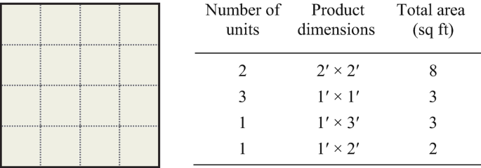
Determine the best arrangement of products on the pallet, where the first two products need to be on the south side of the pallet for flow reasons and the three 1′ × 1′ products should be adjacent to the first two products. Use GMAFLAD to help you find the optimal solution. Is there more than one optimal solution?
-
7.5
Give examples of applications of each of the eight principles of material handling as defined in this chapter.
-
7.6
Differentiate between the following material handling equipment items and give at least three advantages and disadvantages for each type.
-
Spiral chute vs. pneumatic conveyor
-
Belt conveyor vs. wheel conveyor
-
Roller conveyor vs. slat conveyor
-
Lift truck vs. overhead trolley conveyor
-
Hand truck vs. tractor-trailer train
-
Jib hoist vs. bridge crane
-
Automated guided vehicle vs. forklift truck
-
-
7.7
What factors should be considered in choosing the size of a pallet to be used in a factory setting?
-
7.8
Visit a local factory and describe the various material handling devices/systems that you observe. Use a digital camera to record the type of system and possibly include the pictures in your factory project report.
-
7.9
A warehouse uses forklifts to move pallets from receiving to shipping and back again. It takes a forklift around 1 minute to pick up and deposit a pallet and 6 minutes to travel from receiving to shipping and vice versa. The warehouse operates 5 days per week, 8 hours per day. At a minimum, the warehouse manager must be able to move 3000 pallets from receiving to shipping per week. Find the number of forklifts needed to meet the warehouse manager’s pallet demand.
-
7.10
A factory produces 15,000 cellular phones per day. The dimensions of each cell phone are 5 × 2.5 × 2.5 inches. Management wishes to have a 1-week (5-day) supply in stock. One hundred cell phones are packed in a carton, and cartons may be stacked seven high. Determine the floor space required in the warehouse to accommodate the 5-day supply of cell phones.
-
7.11
Use the DSS-MHE code to for three cases where the material handling equipment recommended is (a) a conveyor; (b) a crane; (c) a truck. Create appropriate inference chains for each case.
-
7.12
Modify the example in Fig. 7.37 to consider a case where the primary function of the move is to load or unload material. Design an appropriate inference chain for the case.

References
Apple, J.M. 1972. Material Handling System Design. New York: Ronald Press Company.
———. 1977. Plant Layout and Material Handling. New York: Wiley.
Brown, M., J. Clepper, R. Green, C. Kubesch, and D. Sanchez. 2003. USA Eood Corp., Revolving Desktop Organizer, IE 401 Project Report.
Chan, F.T.S., R.W.L. Ip, and H. Lau. 2001. Integration of Expert System with Analytic Hierarchy Process for the Design of Material Handling Equipment Selection System. Journal of Materials Processing Technology 116 (2–3): 137–145.
Kay, Michael G. Material Handling Equipment Taxonomy. Available through the link https://www.mhi.org/cicmhe/resources/taxonomy.
Konz, Stephan. 1994. Facility Design. 2nd ed. Scottsdale: Publishing Horizons, Inc.
Kulwiec, R. 1984. Trends in Automated Guided Vehicle Systems. Plant Engineering 38: 66–73.
Kulwiec, Raymond A., editor-in-chief. 1985. Materials Handling Handbook, sponsored by the American Society of Mechanical Engineers and the International Material Management Society Edition. 2nd ed. New York: Wiley.
Muther, R., and K. Haganas. 1969. Systematic Handling Analysis. Kansas City: Management and Industrial Research Publications.
Sule, D.R. 1988. Manufacturing Facilities. Boston: PWS-Kent.
Velupula, B. 2003. Development of a Decision-Support System for Material Handling Equipment Selection, MSIE Degree Report. College Station: Department of Industrial and Systems Engineering, Texas A&M University.
Author information
Authors and Affiliations
Rights and permissions
Copyright information
© 2024 The Author(s), under exclusive license to Springer Nature Switzerland AG
About this chapter

Cite this chapter
Garcia-Diaz, A., Smith, J.M. (2024). Material Handling Principles, Equipment, and System Design. In: Facilities Planning and Design. Springer, Cham. https://doi.org/10.1007/978-3-031-54259-6_7
Download citation
DOI: https://doi.org/10.1007/978-3-031-54259-6_7
Published:
Publisher Name: Springer, Cham
Print ISBN: 978-3-031-54258-9
Online ISBN: 978-3-031-54259-6
eBook Packages: EngineeringEngineering (R0)