The selection of specific material types for use in the fabrication of gears ultimately is a balance between needed strength, durability, and cost. This article provides a review of the different metallic and non-metallic gear materials, gear applications, as well as power transmission calculations.
Classification of Gear Steels
Gear steels may be divided into two general classes — the plain carbon and the alloy steels. Alloy steels are used to some extent in the industrial field, but heat-treated plain carbon steels are far more common. The use of untreated alloy steels for gears is seldom, if ever, justified, and then, only when heat-treating facilities are lacking. The points to be considered in determining whether to use heat-treated plain carbon steels or heat-treated alloy steels are: Does the service condition or design require the superior characteristics of the alloy steels, or, if alloy steels are not required, will the advantages to be derived offset the additional cost? For most applications, plain carbon steels, heat-treated to obtain the best of their qualities for the service intended, are satisfactory and quite economical. The advantages obtained from using heat-treated alloy steels in place of heat-treated plain carbon steels are as follows:
- Increased surface hardness and depth of hardness penetration for the same carbon content and quench.
- Ability to obtain the same surface hardness with a less drastic quench and, in the case of some of the alloys, a lower quenching temperature, thus giving less distortion.
- Increased toughness, as indicated by the higher values of yield point, elongation, and reduction of area.
- Finer grain size, with the resulting higher impact toughness and increased wear resistance.
- In the case of some of the alloys, better machining qualities or the possibility of machining at higher hardnesses.
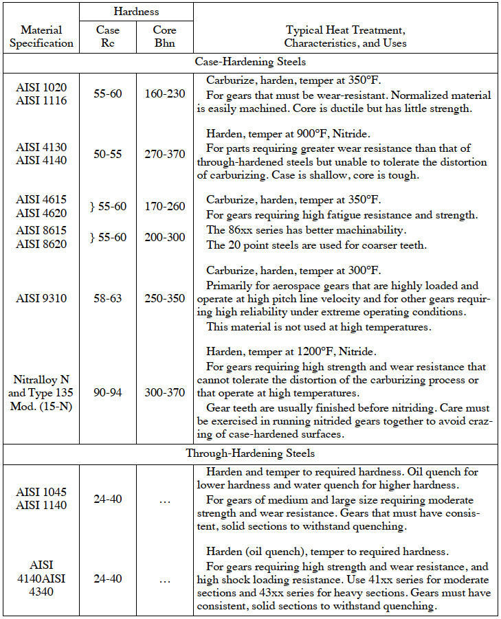
Use of Casehardening Steels
Each of the two general classes of gear steels may be further subdivided as follows: 1) Casehardening steels; 2) full-hardening steels; and 3) steels that are heat-treated and drawn to a hardness that will permit machining.
The first two — casehardening and full-hardening steels — are interchangeable for some kinds of service, and the choice is often a matter of personal opinion. Casehardening steels with their extremely hard, fine-grained (when properly treated) case and comparatively soft and ductile core are generally used when resistance to wear is desired. Casehardening alloy steels have a fairly tough core, but not as tough as that of the full-hardening steels. In order to realize the greatest benefits from the core properties, casehardened steels should be double-quenched. This is particularly true of the alloy steels, because the benefits derived from their use seldom justify the additional expense, unless the core is refined and toughened by a second quench. The penalty that must be paid for the additional refinement is increased distortion, which may be excessive if the shape or design does not lend itself to the casehardening process.
Use of “Thru-Hardening” Steels
Thru-hardening steels are used when great strength, high endurance limit, toughness, and resistance to shock are required. These qualities are governed by the kind of steel and treatment used. Fairly high surface hardnesses are obtainable in this group, though not so high as those of the casehardening steels. For that reason, the resistance to wear is not so great as might be obtained, but when wear resistance combined with great strength and toughness is required, this type of steel is superior to the others. Thru-hardening steels become distorted to some extent when hardened, the amount depending upon the steel and quenching medium used. For that reason, thru-hardening steels are not suitable for high-speed gearing where noise is a factor, or for gearing where accuracy is of paramount importance, except, of course, in cases where grinding of the teeth is practicable. The medium and high-carbon percentages require an oil quench, but a water quench may be necessary for the lower carbon contents, in order to obtain the highest physical properties and hardness. The distortion, however, will be greater with the water quench.
Heat-Treatment that Permits Machining
When the grinding of gear teeth is not practicable and a high degree of accuracy is required, hardened steels may be drawn or tempered to a hardness that will permit the cutting of the teeth. This treatment gives a highly refined structure, great toughness, and, in spite of the low hardness, excellent wearing qualities. The lower strength is somewhat compensated for by the elimination of the increment loads due to the impacts which are caused by inaccuracies. When steels that have a low degree of hardness penetration from surface to core are treated in this manner, the design cannot be based on the physical properties corresponding to the hardness at the surface. Since the physical properties are determined by the hardness, the drop in hardness from surface to core will give lower physical properties at the root of the tooth, where the stress is greatest. The quenching medium may be either oil, water, or brine, depending on the steel used and hardness penetration desired. The amount of distortion, of course, is immaterial, because the machining is done after heat-treating.
Making Pinion Harder than Gear to Equalize Wear
Beneficial results from a wear standpoint are obtained by making the pinion harder than the gear. The pinion, having a lesser number of teeth than the gear, naturally does more work per tooth, and the differential in hardness between the pinion and the gear (the amount being dependent on the ratio) serves to equalize the rate of wear. The harder pinion teeth correct the errors in the gear teeth to some extent by the initial wear and then seem to burnish the teeth of the gear and increase its ability to withstand wear by the greater hardness due to the cold-working of the surface. In applications where the gear ratio is high and there are no severe shock loads, a casehardened pinion running with an oil-treated gear, treated to a Brinell hardness at which the teeth may be cut after treating, is an excellent combination. The pinion, being relatively small, is distorted but little, and distortion in the gear is circumvented by cutting the teeth after treatment.
Forged and Rolled Carbon Steels for Gears
These compositions cover steel for gears in three groups, according to heat treatment, as follows:
a) case-hardened gears
b) unhardened gears, not heat treated after machining
c) hardened and tempered gears
Forged and rolled carbon gear steels are purchased on the basis of the requirements as to chemical composition specified in Table 1. Class N steel will normally be ordered in ten point carbon ranges within these limits. Requirements as to physical properties have been omitted, but when they are called for the requirements as to carbon shall be omitted. The steels may be made by either or both the open hearth and electric furnace processes.
Table 1. Compositions of Forged and Rolled Carbon Steels for Gears
| Heat Treatment | Class | Carbon | Manganese | Phosphorus | Sulfur |
| Case-hardened Untreated Hardened (or untreated) |
C N H |
0.15-0.25 0.25-0.50 0.40-0.50 |
0.40-0.70 0.50-0.80 0.40-0.70 |
0.045 max 0.045 max 0.045 max |
0.055 max 0.055 max 0.055 max |
Forged and Rolled Alloy Steels for Gears
These compositions cover alloy steel for gears, in two classes according to heat treatment, as follows:
a) case-hardened gears
b) hardened and tempered gears
Forged and rolled alloy gear steels are purchased on the basis of the requirements as to chemical composition specified in Table 2. Requirements as to physical properties have been omitted. The steel shall be made by either or both the open hearth and electric furnace process.
Table 2. Compositions of Forged and Rolled Alloy Steels for Gears
|
Steel
|
Chemical Composition a | |||||
| C | Mn | Si | Ni | Cr | Mo | |
| AISI 4130 AISI 4140 AISI 4340 AISI 4615 AISI 4620 AISI 8615 AISI 8620 AISI 9310 Nitralloy Type Nb 135 Mod.b |
0.28–0.30 0.20–0.27 |
0.40–0.60 0.40–0.70 |
0.20–0.35 0.20–0.40 |
… 3.2–3.8 |
0.80–1.1 1.0–1.3 |
0.15–0.25 0.20–0.30 |
a C = carbon; Mn = manganese; Si = silicon; Ni = nickel; Cr = chromium, and Mo = molybdenum.
b Both Nitralloy alloys contain aluminum 0.85–1.2%
Steel Castings for Gears
It is recommended that steel castings for cut gears be purchased on the basis of chemical analysis and that only two types of analysis be used, one for case-hardened gears and the other for both untreated gears and those which are to be hardened and tempered. The steel is to be made by the open hearth, crucible, or electric furnace processes. The converter process is not recognized. Sufficient risers must be provided to secure soundness and freedom from undue segregation. Risers should not be broken off the unannealed castings by force. Where risers are cut off with a torch, the cut should be at least one-half inch above the surface of the castings, and the remaining metal removed by chipping, grinding, or other noninjurious method.
Steel for use in gears should conform to the requirements for chemical composition indicated in Table 3. All steel castings for gears must be thoroughly normalized or annealed, using such temperature and time as will entirely eliminate the characteristic structure of unannealed castings.
Table 3. Compositions of Cast Steels for Gears
| Steel Specification |
Chemical Composition a | |||
| C | Mn | Si | ||
| SAE-0022 SAE-0050 |
0.12-0.22 0.40-0.50 |
0.50-0.90 0.50-0.90 |
0.60 Max. 0.80 Max. |
May be carburized Hardenable 210-250 |
a C = carbon; Mn = manganese; and Si = silicon.
Effect of Alloying Metals on Gear Steels
The effect of the various alloying elements on steel are here summarized to assist in deciding on the particular kind of alloy steel to use for specific purposes. The characteristics outlined apply only to heat-treated steels. When the effect of the addition of an alloying element is stated, it is understood that reference is made to alloy steels of a given carbon content, compared with a plain carbon steel of the same carbon content.
Nickel: The addition of nickel tends to increase the hardness and strength, with but little sacrifice of ductility. The hardness penetration is somewhat greater than that of plain carbon steels. Use of nickel as an alloying element lowers the critical points and produces less distortion, due to the lower quenching temperature. The nickel steels of the case-hardening group carburize more slowly, but the grain growth is less.
Chromium: Chromium increases the hardness and strength over that obtained by the use of nickel, though the loss of ductility is greater. Chromium refines the grain and imparts a greater depth of hardness. Chromium steels have a high degree of wear resistance and are easily machined in spite of the fine grain.
Manganese: When present in sufficient amounts to warrant the use of the term alloy, the addition of manganese is very effective. It gives greater strength than nickel and a higher degree of toughness than chromium. Owing to its susceptibility to cold-working, it is likely to flow under severe unit pressures. Up to the present time, it has never been used to any great extent for heat-treated gears, but is now receiving an increasing amount of attention.
Vanadium: Vanadium has a similar effect to that of manganese—increasing the hardness, strength, and toughness. The loss of ductility is somewhat more than that due to manganese, but the hardness penetration is greater than for any of the other alloying elements. Owing to the extremely fine-grained structure, the impact strength is high; but vanadium tends to make machining difficult.
Molybdenum: Molybdenum has the property of increasing the strength without affecting the ductility. For the same hardness, steels containing molybdenum are more ductile than any other alloy steels, and having nearly the same strength, are tougher; in spite of the increased toughness, the presence of molybdenum does not make machining more difficult. In fact, such steels can be machined at a higher hardness than any of the other alloy steels. The impact strength is nearly as great as that of the vanadium steels.
Chrome-Nickel Steels: The combination of the two alloying elements chromium and nickel adds the beneficial qualities of both. The high degree of ductility present in nickel steels is complemented by the high strength, finer grain size, deep hardening, and wear-resistant properties imparted by the addition of chromium. The increased toughness makes these steels more difficult to machine than the plain carbon steels, and they are more difficult to heat treat. The distortion increases with the amount of chromium and nickel.
Chrome-Vanadium Steels: Chrome-vanadium steels have practically the same tensile properties as the chrome-nickel steels, but the hardening power, impact strength, and wear resistance are increased by the finer grain size. They are difficult to machine and become distorted more easily than the other alloy steels.
Chrome-Molybdenum Steels: This group has the same qualities as the straight molybdenum steels, but the hardening depth and wear resistance are increased by the addition of chromium. This steel is very easily heat treated and machined.
Nickel-Molybdenum Steels: Nickel-molybdenum steels have qualities similar to chrome-molybdenum steel. The toughness is said to be greater, but the steel is somewhat more difficult to machine.
Sintered Materials
For high production of low and moderately loaded gears, significant production cost savings may be effected by the use of a sintered metal powder. With this material, the gear is formed in a die under high pressure and then sintered in a furnace. The primary cost saving comes from the great reduction in labor cost of machining the gear teeth and other gear blank surfaces. The volume of production must be high enough to amortize the cost of the die and the gear blank must be of such a configuration that it may be formed and readily ejected from the die.
Bronze and Brass Gear Castings
These specifications cover nonferrous metals for spur, bevel, and worm gears, bushings and flanges for composition gears. This material shall be purchased on the basis of chemical composition. The alloys may be made by any approved method.
Spur and Bevel Gears: For spur and bevel gears, hard cast bronze is recommended (ASTM B-10-18; SAE No. 62; and the well-known 88-10-2 mixture) with the following limits as to composition: Copper, 86 to 89; tin, 9 to 11; zinc, 1 to 3; lead (max), 0.20; iron (max), 0.06 percent. Good castings made from this bronze should have the following minimum physical characteristics: Ultimate strength, 30,000 pounds per square inch; yield point, 15,000 pounds per square inch; elongation in 2 inches, 14 percent.
Steels for Industrial Gearing
Worm Gears: For bronze worm gears, two alternative analyses of phosphor bronze are recommended, SAE No. 65 and No. 63.
SAE No. 65 (called phosphor gear bronze) has the following composition: Copper, 88 to 90; tin, 10 to 12; phosphorus, 0.1 to 0.3; lead, zinc, and impurities (max) 0.5 percent.
Good castings made of this alloy should have the following minimum physical characteristics: Ultimate strength, 35,000 pounds per square inch; yield point, 20,000 pounds per square inch; elongation in 2 inches, 10 percent.
The composition of SAE No. 63 (called leaded gun metal) follows: copper, 86 to 89; tin, 9 to 11; lead, 1 to 2.5; phosphorus (max), 0.25; zinc and impurities (max), 0.50 percent.
Good castings made of this alloy should have the following minimum physical characteristics: Ultimate strength, 30,000 pounds per square inch; yield point, 12,000 pounds per square inch; elongation in 2 inches, 10 percent.
These alloys, especially No. 65, are adapted to chilling for hardness and refinement of grain. No. 65 is to be preferred for use with worms of great hardness and fine accuracy. No. 63 is to be preferred for use with unhardened worms.
Gear Bushings: For bronze bushings for gears, SAE No. 64 is recommended of the following analysis: copper, 78.5 to 81.5; tin, 9 to 11; lead, 9 to 11; phosphorus, 0.05 to 0.25; zinc (max), 0.75; other impurities (max), 0.25 percent. Good castings of this alloy should have the following minimum physical characteristics: Ultimate strength, 25,000 pounds per square inch; yield point, 12,000 pounds per square inch; elongation in 2 inches, 8 percent.
Flanges for Composition Pinions: For brass flanges for composition pinions ASTM B-30-32T, and SAE No. 40 are recommended. This is a good cast red brass of sufficient strength and hardness to take its share of load and wear when the design is such that the flanges mesh with the mating gear. The composition is as follows: copper, 83 to 86; tin, 4.5 to 5.5; lead, 4.5 to 5.5; zinc, 4.5 to 5.5; iron (max) 0.35; antimony (max), 0.25 percent; aluminum, none. Good castings made from this alloy should have the following minimum physical characteristics: ultimate strength, 27,000 pounds per square inch; yield point, 12,000 pounds per square inch; elongation in 2 inches, 16 percent.
Materials for Worm Gearing
The Hamilton Gear & Machine Co. conducted an extensive series of tests on a variety of materials that might be used for worm gears, to ascertain which material is the most suitable. According to these tests chill-cast nickel-phosphor-bronze ranks first in resistance to wear and deformation. This bronze is composed of approximately 87.5 percent copper, 11 percent tin, 1.5 percent nickel, with from 0.1 to 0.2 percent phosphorus. The worms used in these tests were made from SAE-2315, 3 ½ percent nickel steel, case-hardened, ground, and polished. The Shore scleroscope hardness of the worms was between 80 and 90. This nickel alloy steel was adopted after numerous tests of a variety of steels, because it provided the necessary strength, together with the degree of hardness required.
The material that showed up second best in these tests was a No. 65 SAE bronze. Navy bronze (88-10-2) containing 2 percent zinc, with no phosphorus, and not chilled, performed satisfactorily at speeds of 600 revolutions per minute, but was not sufficiently strong at lower speeds. Red brass (85-5-5) proved slightly better at from 1500 to 1800 revolutions per minute, but would bend at lower speeds, before it would show actual wear.
Non-metallic Gearing
Non-metallic or composition gearing is used primarily where quietness of operation at high speed is the first consideration. Non-metallic materials are also applied very generally to timing gears and numerous other classes of gearing. Rawhide was used originally for non-metallic gears, but other materials have been introduced that have important advantages. These later materials are sold by different firms under various trade names, such as Micarta, Textolite, Formica, Dilecto, Spauldite, Phenolite, Fibroc, Fabroil, Synthane, Celoron, etc. Most of these gear materials consist of layers of canvas or other material that is impregnated with plastics and forced together under hydraulic pressure, which, in conjunction with the application of heat, forms a dense rigid mass.
Although phenol resin gears in general are resilient, they are self-supporting and require no side plates or shrouds unless subjected to a heavy starting torque. The phenol resinoid element protects these gears from vermin and rodents.
The non-metallic gear materials referred to are generally assumed to have the power transmitting capacity of cast iron. Although the tensile strength may be considerably less than that of cast iron, the resiliency of these materials enables them to withstand impact and abrasion to a degree that might result in excessive wear of cast-iron teeth. Thus, composition gearing of impregnated canvas has often proved to be more durable than cast iron.
Application of Non-metallic Gears
The most effective field of use for these nonmetallic materials is for high-speed duty. At low speeds, when the starting torque may be high, or when the load may fluctuate widely, or when high shock loads may be encountered, these non-metallic materials do not always prove satisfactory. In general, nonmetallic materials should not be used for pitch-line velocities below 600 feet per minute (3.05 m/s).
Tooth Form: The best tooth form for non-metallic materials is the 20-degree stub-tooth system. When only a single pair of gears is involved and the center distance can be varied, the best results will be obtained by making the non-metallic driving pinion of all-addendum form, and the driven metal gear with standard tooth proportions. Such a drive will carry from 50 to 75 percent greater loads than one of standard tooth proportions.
Material for Mating Gear: For durability under load, the use of hardened steel (over 400 Brinell) for the mating metal gear appears to give the best results. A good second choice for the material of the mating member is cast iron. The use of brass, bronze, or soft steel (under 400 Brinell) as a material for the mating member of phenolic laminated gears leads to excessive abrasive wear.
Power-Transmitting Capacity of Non-metallic Gears
The characteristics of gears made of phenolic laminated materials are so different from those of metal gears that they should be considered in a class by themselves. Because of the low modulus of elasticity, most of the effects of small errors in tooth form and spacing are absorbed at the tooth surfaces by the elastic deformation, and have but little effect on the strength of the gears.
If
S = safe working stress for a given velocity ib/in2 (MPa)
Ss = allowable static stress lb/in2 (MPa)
V = pitch-line velocity in feet per minute (meter/s)
then, the recommended practice of the American Gear Manufacturers’ Association,

The value of Ss for phenolic laminated materials is given as 6000 lb/in2 (41.36 MPa). The accompanying table gives the safe working stresses S for different pitch-line velocities. When the value of S is known, the horsepower capacity is determined by substituting the value of S for Ss in the appropriate equations in the section on power-transmitting capacity of plastics gears starting on page 592.
Safe Working Stresses for Non-metallic Gears
| Pitch-Line Velocity, V |
Safe Working Stress, S |
Pitch-Line Velocity, V |
Safe Working Stress, S |
Pitch-Line Velocity, V |
Safe Working Stress, S |
||||||
| fpm | m/s | lb/in2 | MPa | fpm | m/s | lb/in2 | MPa | fpm | m/s | lb/in2 | MPa |
| 600 700 800 900 1000 1200 1400 1600 |
3.05 3.56 4.06 4.57 5.08 6.10 7.11 8.13 |
2625 2500 2400 2318 2250 2143 2063 2000 |
18.10 17.24 16.54 15.98 15.51 14.78 14.22 13.79 |
1800 2000 2200 2400 2600 2800 3000 3500 |
9.14 10.16 11.18 12.19 13.20 14.22 15.24 17.78 |
1950 1909 1875 1846 1821 1800 1781 1743 |
13.44 13.16 12.93 12.73 12.56 12.41 12.28 12.02 |
4000 4500 5000 5500 6000 6500 7000 7500 |
20.32 22.86 25.40 27.94 30.48 33.02 35.56 38.10 |
1714 1691 1673 1653 1645 1634 1622 1617 |
11.82 11.66 11.53 11.40 11.34 11.27 11.18 11.15 |
The tensile strength of the phenolic laminated materials used for gears is slightly less than that of cast iron. These materials are far softer than any metal, and the modulus of elasticity is about one-thirtieth that of steel. In other words, if the tooth load on a steel gear that causes a deformation of 0.001 inch (0.025 mm) were applied to the tooth of a similar gear made of phenolic laminated material, the tooth of the non-metallic gear would be deformed about 1⁄32 inch (0.794 mm). Under these conditions, several things will happen. With all gears, regardless of the theoretical duration of contact, one tooth only will carry the load until the load is sufficient to deform the tooth the amount of the error that may be present. On metal gears, when the tooth has been deformed the amount of the error, the stresses set up in the materials may approach or exceed the elastic limit of the material. Hence, for standard tooth forms and those generated from standard basic racks, it is dangerous to calculate their strength as very much greater than that which can safely be carried on a single tooth. On gears made of phenolic laminated materials, on the other hand, the teeth will be deformed the amount of this normal error without setting up any appreciable stresses in the material, so that the load is actually supported by several teeth.
All materials have their own peculiar and distinct characteristics, so that under certain specific conditions, each material has a field of its own where it is superior to any other. Such fields may overlap to some extent, and only in such overlapping fields are different materials directly competitive. For example, steel is more or less ductile, has a high tensile strength, and a high modulus of elasticity. Cast iron, on the other hand, is not ductile, has a low tensile strength, but a high compressive strength, and a low modulus of elasticity. Hence, when stiffness and high tensile strength are essential, steel is far superior to cast iron. On the other hand, when these two characteristics are unimportant, but high compressive strength and a moderate amount of elasticity are essential, cast iron is superior to steel.
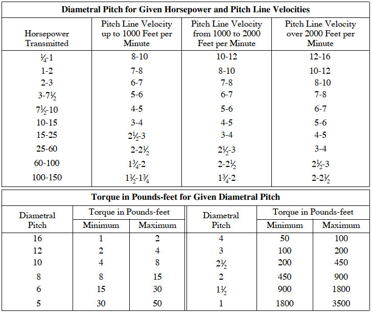
Preferred Pitch for Non-metallic Gears
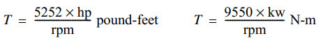
The pitch of the gear or pinion should bear a reasonable relation either to the power or speed or to the applied torque, as shown by the accompanying table. The upper half of this table is based upon horsepower (kw) transmitted at a given pitch-line velocity. The lower half gives the torque in pounds-feet (N-m) or the torque at a 1-foot (meter) radius. This torque T for any given horsepower (kw) and speed can be obtained from the following formulas:
Bore Sizes for Non-metallic Gears
For plain phenolic laminated pinions, that is, pinions without metal end plates, a drive fit of 0.001 inch per inch(or mm/mm) of shaft diameter should be used. For shafts above 2.5 inches(63.5 mm) in diameter, the fit should be constant at 0.0025 to 0.003 inch(0.064–0.076 mm). When metal reinforcing end plates are used, the drive fit should conform to the same standards as used for metal.
The root diameter of a pinion of phenolic laminated type should be such that the minimum distance from the edge of the keyway to the root diameter will be at least equal to the depth of tooth.
Keyway Stresses for Non-metallic Gears
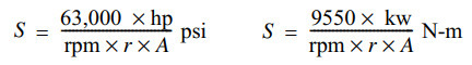
The keyway stress should not exceed 3000 psi (20.68 MPa) on a plain phenolic laminated gear or pinion. The keyway stress is calculated by the formulas:
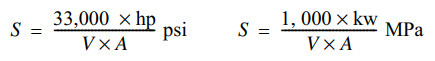
where
S =unit stress in pounds per square inch (newton per square meter)
hp = horsepower transmitted
kw =kilowatt power transmitted
V =peripheral speed of shaft in feet per minute (meter/sec)
A =square inch (square meter) area of keyway in pinion (length × height)
If the keyway stress formula is expressed in terms of shaft radius r (inch or meter) and revolutions per minute, it will read:
Preferred Pitches for Non-metallic Gears
Applicable both to rawhide and the phenolic laminated types of materials
When the design is such that the keyway stresses exceed 3000 psi (20.68 MPa), metal reinforcing end plates may be used. Such end plates should not extend beyond the root diameter of the teeth. The distance from the outer edge of the retaining bolt to the root diameter of the teeth shall not be less than a full tooth depth. The use of drive keys should be avoided, but if required, metal end plates should be used on the pinion to take the wedging action of the key.
For phenolic laminated pinions, the face of the mating gear should be the same or slightly greater than the pinion face.
Summary
This article provided a review of the different metallic and non-metallic gear materials, gear applications, as well as power transmission calculations. Learn more about gearing from the Machinery’s Handbook, 30th Edition, which is published and available from Industrial Press on Amazon.
To locate sources of supply for gears, visit the Thomas Supplier Discovery Platform where you can locate potential sources of supply for over 70,000 different product and service categories.
Other Gears Articles
- Types of Sprockets – A Thomas Buying Guide
- All About Spur Gears – What they Are and How They Work
- About Clutches – A Brief Guide
- Understanding Gears
- All About Bevel Gears – What they Are and How They Work
- All About Helical Gears – What They Are and How They Work
- All About Worm Gears – What They Are and How They Work
- All About Rack and Pinion Gears – What They Are and How They Work
- Definitions of Gear Terminology
- Top Gears Manufacturers and Suppliers

