
Feasibility Studies on the Utilization of Recycled Slag in Grouting Material for Tunneling Engineering
 and
and
Abstract
:1. Introduction
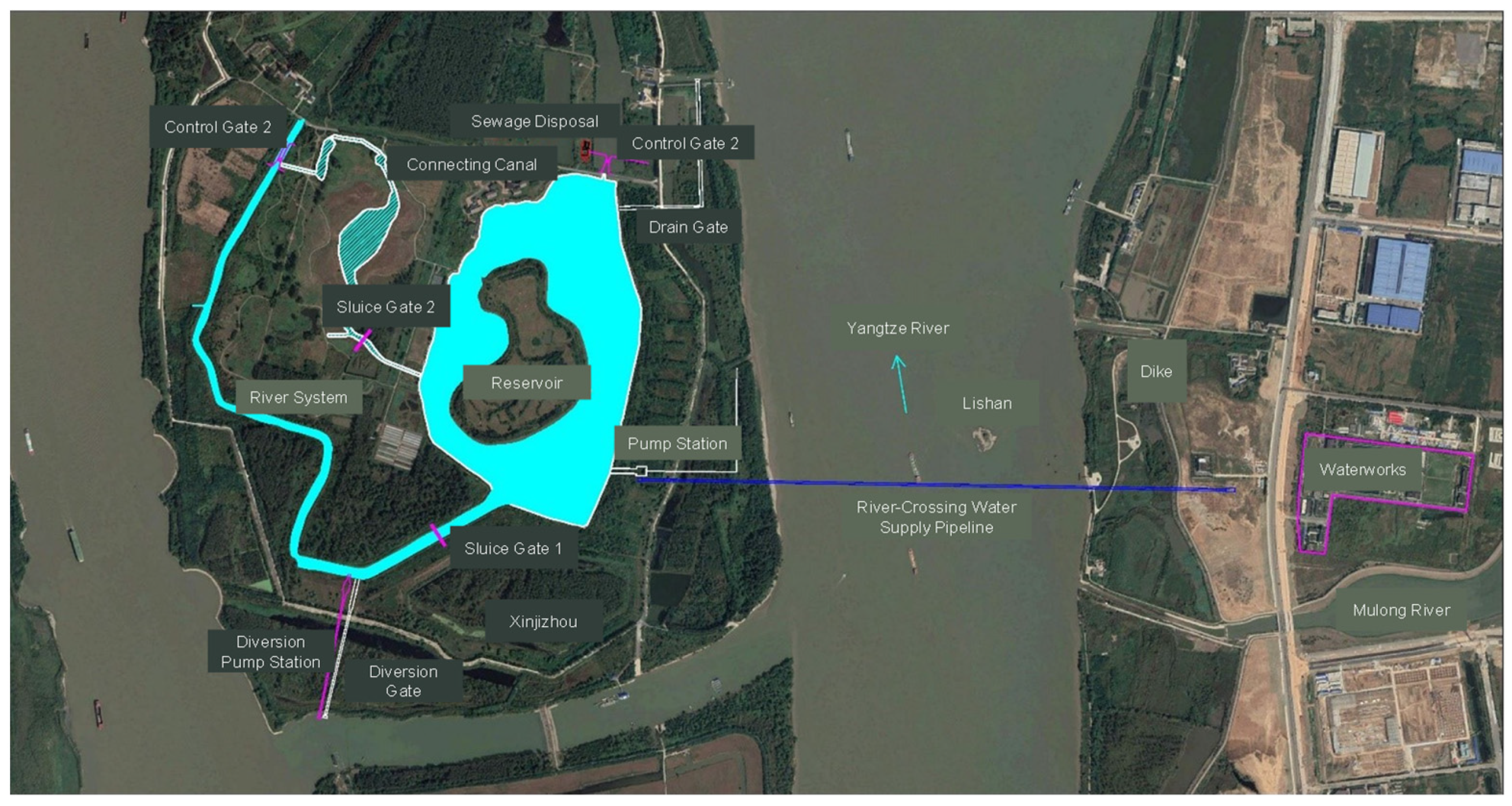
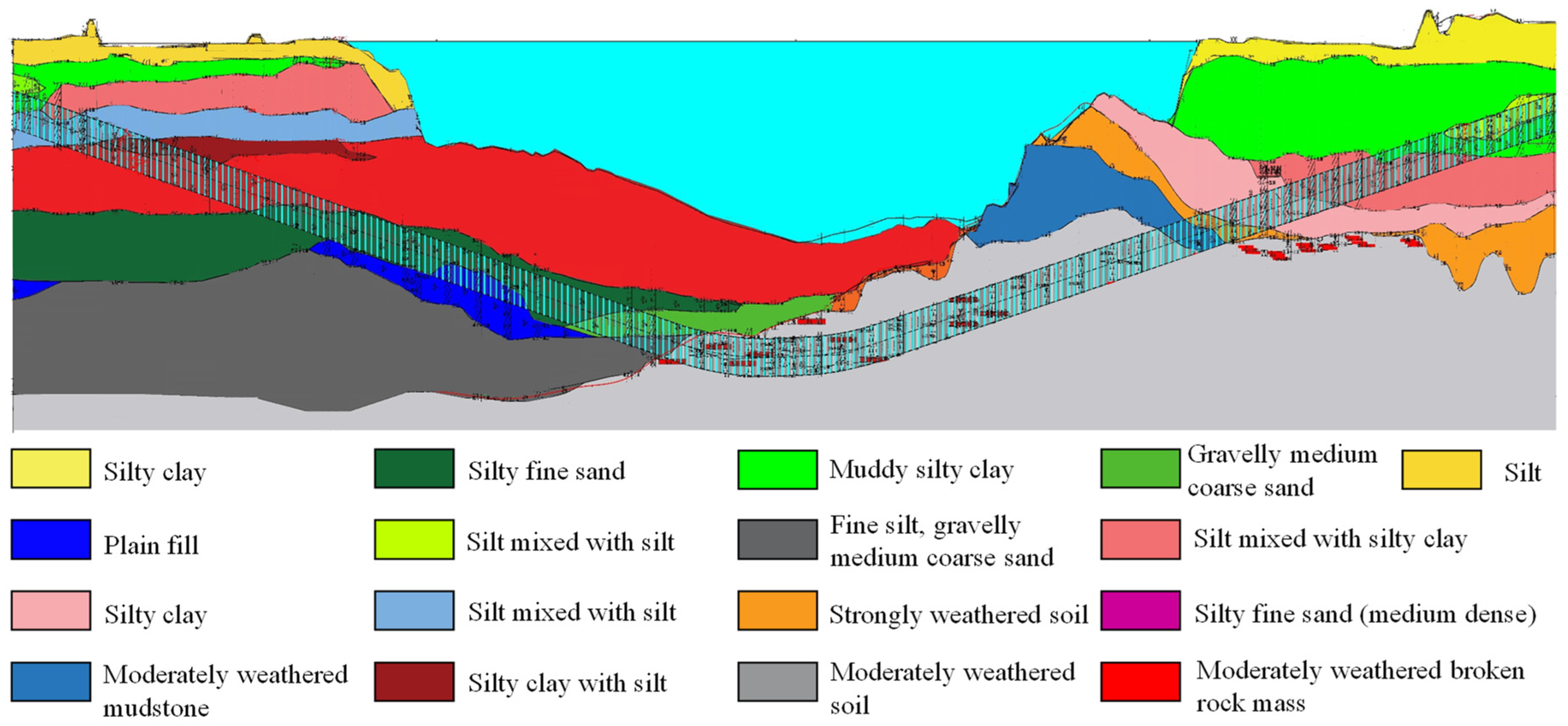
2. Project Background
3. Experimental Program
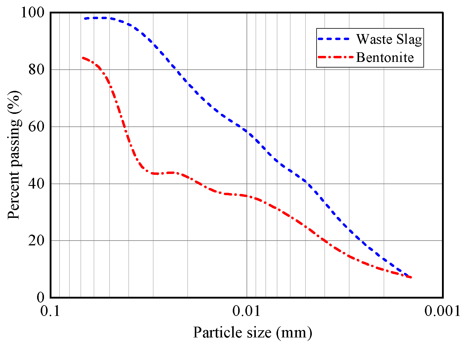
3.1. Test Material and Sample Preparation
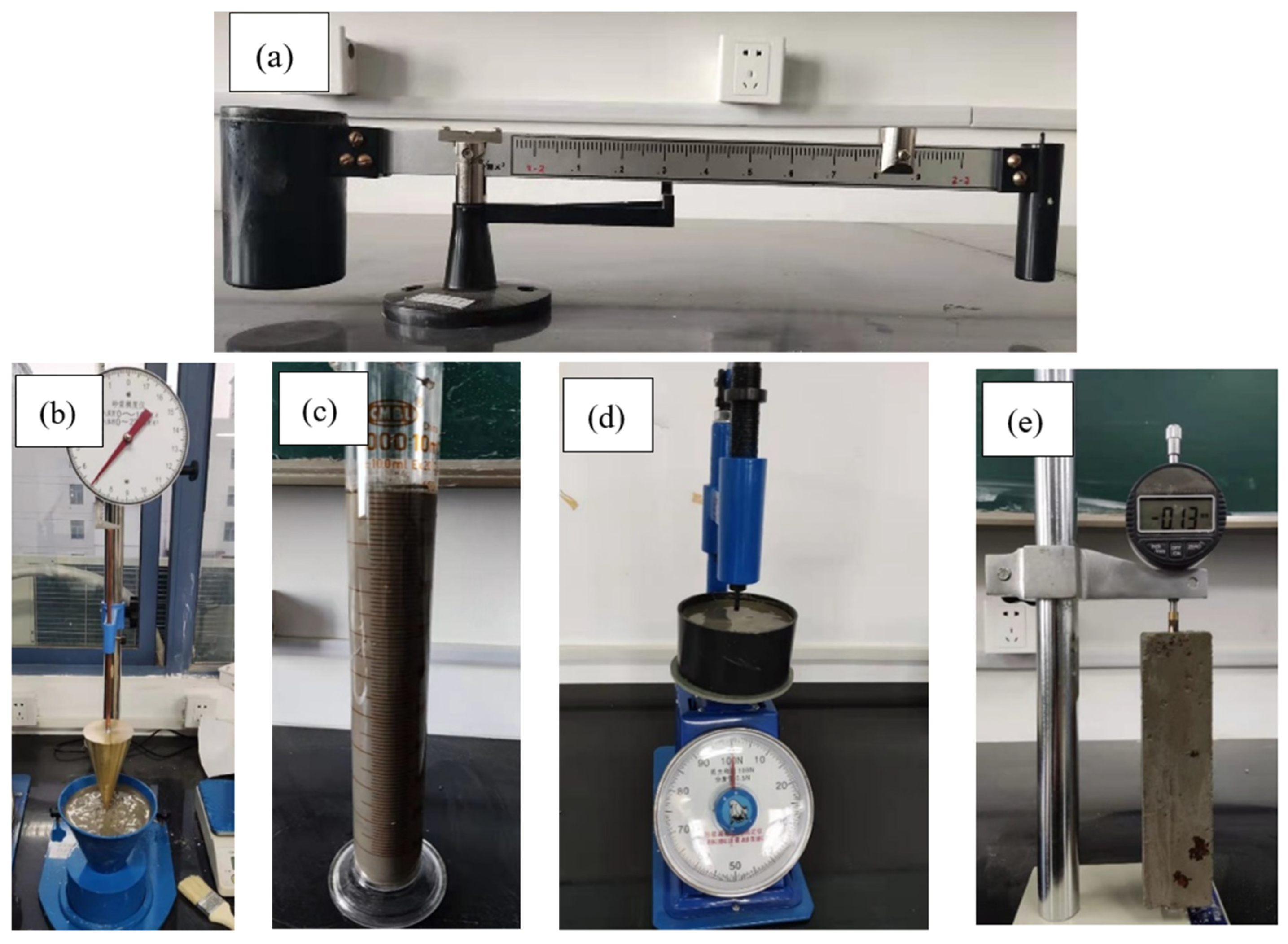
3.2. Testing Apparatus and the Orthogonal Test
4. Results and Discussion
5. Conclusions
- The grouting material with the selected proportions of waste slag has similar engineering properties to the grouting material following the design mix. This indicates that waste slag can be reused in grouting materials for tunneling engineering.
- The orthogonal test was adopted to minimize the number of specimens required for the measurements. The efficiency of the experimental studies was thus significantly improved.
- A new equation was proposed for the rough estimation of the engineering properties of grouting material with different proportions of waste slag.
- The engineering properties of the grouting material based on the design mix can be used as the reference in the evaluation of the feasibility of recycling waste slag for tunneling engineering.
Author Contributions
Funding
Institutional Review Board Statement
Informed Consent Statement
Conflicts of Interest
References
- Wang, Z.; Wu, X.; Lu, Q.; Peng, G.; Jiang, H.; Zhang, H.; Liu, Y.; Feng, X. Study on the field processing technology of engineering slurry. West-China Explor. Eng. 2018, 4, 23–25. [Google Scholar]
- Yin, Y.; Li, B.; Wang, W.; Zhan, L.; Xue, Q.; Gao, Y.; Zhang, L.; Chen, H.; Liu, T.; Li, A. Mechanism of the December 2015 catastrophic landslide at the Shenzhen landfill and controlling geotechnical risks of urbanization. Engineering 2016, 2, 230–249. [Google Scholar] [CrossRef]
- Yu, C.; Zhou, A.; Chen, J.; Arulrajah, A.; Horpibulsuk, S. Analysis of a tunnel failure caused by leakage of the shield tail seal system. Undergr. Space 2020, 5, 105–114. [Google Scholar] [CrossRef]
- Helmut, G. Cost-efficient Regeneration of Bore Slurry for Driving of Weser Tunnel. Tunn. Constr. 2007, 27, 47–51. [Google Scholar]
- Chen, X.; Zhu, W.; Wang, R.; Min, F.; Wei, D. Application of Waste Sand in Backfilling Grouting in Shielding Tunneling: Case Study on Weisanlu River-crossing Tunnel in Nanjing. Tunn. Constr. 2015, 35, 1176–1181. [Google Scholar]
- Xu, K. The Research and Application on High-Performance Grouting Made by Shield Sediment. Master’s Thesis, Wuhan University of Technology, Wuhan, China, 2011. [Google Scholar]
- Zhang, Y.; Xia, P.; Wei, D.; Jiang, T.; Chen, X.; Lu, S. Slurry Treatment and Waste Muck Recycling Use in Construction of Weisanlu Yangtze River Crossing Tunnel in Nanjing. Tunn. Constr. 2015, 35, 1229–1233. [Google Scholar]
- Zhong, X.; Zuo, J.; Liu, Q.; Han, Y. Reuse of excavated fine sand for back grouting of shield tunnelling. Rock Soil Mech. 2008, 29, 293–296. [Google Scholar]
- Yang, Z.; He, Z.; Wu, K. Study of Application of Waste Slurry to Backfilled Grouting of Shield Tunnel. Tunn. Constr. 2017, 37, 985–989. [Google Scholar]
- Zhou, S.; Li, X.; Ji, C.; Xiao, J. Back-fill grout experimental test for discharged soils reuse of the large-diameter size slurry shield tunnel. KSCE J. Civ. Eng. 2017, 21, 725–733. [Google Scholar] [CrossRef]
- Zhang, D.; Sun, Z.; Fang, Q. Scientific problems and research proposals for Sichuan-Tibet railway tunnel construction. Undergr. Space 2022, 7, 419–439. [Google Scholar] [CrossRef]
- Sun, Z.; Zhang, D.; Fang, Q.; Liu, D.; Dui, G. Displacement process analysis of deep tunnels with grouted rockbolts considering bolt installation time and bolt length. Comput. Geotech. 2021, 140, 104437. [Google Scholar] [CrossRef]
- Sun, Z.; Zhang, D.; Fang, Q.; Dui, G.; Tai, Q.; Sun, F. Analysis of the interaction between tunnel support and surrounding rock considering pre-reinforcement. Tunn. Undergr. Space Technol. 2021, 115, 104074. [Google Scholar] [CrossRef]
- Sun, Z.; Zhang, D.; Fang, Q.; Dui, G.; Chu, Z. Analytical solutions for deep tunnels in strain-softening rocks modeled by different elastic strain definitions with the unified strength theory. Sci. China Technol. Sci. 2022, 65. [Google Scholar] [CrossRef]
- JGJ/T 70—2009; Standard for Test Method of Performance on Building Mortar. Shaanxi Academy of Architectural Sciences Co., Ltd.; China Architecture & Building Press: Beijing, China, 2009.
- GB/T 25182-2010; Grouting Admixture for Prestressed Structure. China Academy of Building Research; Standards Press of China: Beijing, China, 2010.


| Material | Specifications |
|---|---|
| Cement | 42.5R ordinary Portland cement |
| Coal fly ash | Grade II coal fly ash, 200 mesh |
| Bentonite | Grade I sodium bentonite |
| Sand | 0.075~2 mm |
| Water | pH = 7 |
| Levels | Water–Binder Ratio | Binder–Sand Ratio | Bentonite–Water Ratio | Coal Fly Ash–Cement Ratio |
|---|---|---|---|---|
| 1 | 0.6 | 0.60 | 0.08 | 1.8 |
| 2 | 0.7 | 0.66 | 0.12 | 2.4 |
| 3 | 0.8 | 0.72 | 0.16 | 3.0 |
| 4 | 0.9 | 0.78 | 0.20 | 3.6 |
| 5 | 1.0 | 0.84 | 0.24 | 4.2 |
| Factors | Water–Binder Ratio | Binder–Sand Ratio | Bentonite–Water Ratio | Coal Fly Ash–Cement Ratio |
|---|---|---|---|---|
| 1 | 0.60 | 0.60 | 0.08 | 1.80 |
| 2 | 0.60 | 0.66 | 0.12 | 2.40 |
| 3 | 0.60 | 0.72 | 0.16 | 3.00 |
| 4 | 0.60 | 0.78 | 0.20 | 3.60 |
| 5 | 0.60 | 0.84 | 0.24 | 4.20 |
| 6 | 0.70 | 0.60 | 0.12 | 3.00 |
| 7 | 0.70 | 0.66 | 0.16 | 3.60 |
| 8 | 0.70 | 0.72 | 0.20 | 4.20 |
| 9 | 0.70 | 0.78 | 0.24 | 1.80 |
| 10 | 0.70 | 0.84 | 0.08 | 2.40 |
| 11 | 0.80 | 0.60 | 0.16 | 4.20 |
| 12 | 0.80 | 0.66 | 0.20 | 1.80 |
| 13 | 0.80 | 0.72 | 0.24 | 2.40 |
| 14 | 0.80 | 0.78 | 0.08 | 3.00 |
| 15 | 0.80 | 0.84 | 0.12 | 3.60 |
| 16 | 0.90 | 0.60 | 0.20 | 2.40 |
| 17 | 0.90 | 0.66 | 0.24 | 3.00 |
| 18 | 0.90 | 0.72 | 0.08 | 3.60 |
| 19 | 0.90 | 0.78 | 0.12 | 4.20 |
| 20 | 0.90 | 0.84 | 0.16 | 1.80 |
| 21 | 1.00 | 0.60 | 0.24 | 3.60 |
| 22 | 1.00 | 0.66 | 0.08 | 4.20 |
| 23 | 1.00 | 0.72 | 0.12 | 1.80 |
| 24 | 1.00 | 0.78 | 0.16 | 2.40 |
| 25 | 1.00 | 0.84 | 0.20 | 3.00 |
| Reference group | 1.15 | 0.96 | 0.15 | 1.67 |
| Factors | Cement (g) | Coal Fly Ash (g) | Waste Slag (or Bentonite) (g) | Sand (g) | Water (g) | Total Weight (g) |
|---|---|---|---|---|---|---|
| 1 | 215.5 | 387.9 | 29.0 | 1005.6 | 362.0 | 2000.0 |
| 2 | 184.6 | 443.0 | 45.2 | 950.8 | 376.5 | 2000.0 |
| 3 | 162.1 | 486.2 | 62.2 | 900.4 | 389.0 | 2000.0 |
| 4 | 144.8 | 521.4 | 79.9 | 854.1 | 399.7 | 2000.0 |
| 5 | 131.1 | 550.5 | 98.1 | 811.4 | 408.9 | 2000.0 |
| 6 | 144.9 | 434.7 | 48.7 | 966.0 | 405.7 | 2000.0 |
| 7 | 130.7 | 470.4 | 67.3 | 910.8 | 420.8 | 2000.0 |
| 8 | 119.1 | 500.3 | 86.7 | 860.3 | 433.6 | 2000.0 |
| 9 | 226.8 | 408.2 | 106.7 | 814.0 | 444.4 | 2000.0 |
| 10 | 199.6 | 479.1 | 38.0 | 808.1 | 475.1 | 2000.0 |
| 11 | 107.0 | 449.4 | 71.2 | 927.3 | 445.1 | 2000.0 |
| 12 | 205.5 | 370.0 | 92.1 | 872.0 | 460.4 | 2000.0 |
| 13 | 174.0 | 417.6 | 113.6 | 821.6 | 473.2 | 2000.0 |
| 14 | 158.9 | 476.8 | 40.7 | 815.0 | 508.6 | 2000.0 |
| 15 | 140.9 | 507.1 | 62.2 | 771.4 | 518.4 | 2000.0 |
| 16 | 157.0 | 376.8 | 96.1 | 889.7 | 480.4 | 2000.0 |
| 17 | 137.7 | 413.1 | 119.0 | 834.5 | 495.7 | 2000.0 |
| 18 | 129.4 | 465.7 | 42.8 | 826.5 | 535.6 | 2000.0 |
| 19 | 116.9 | 491.0 | 65.7 | 779.4 | 547.1 | 2000.0 |
| 20 | 220.8 | 397.5 | 89.0 | 736.1 | 556.5 | 2000.0 |
| 21 | 111.3 | 400.7 | 122.9 | 853.2 | 511.9 | 2000.0 |
| 22 | 107.0 | 449.3 | 44.5 | 842.9 | 556.3 | 2000.0 |
| 23 | 203.6 | 366.4 | 68.4 | 791.6 | 570.0 | 2000.0 |
| 24 | 170.9 | 410.2 | 93.0 | 744.9 | 581.0 | 2000.0 |
| 25 | 147.5 | 442.4 | 118.0 | 702.2 | 589.9 | 2000.0 |
| Reference group | 223.6 | 372.7 | 99.4 | 621.1 | 683.2 | 2000.0 |
| Index | Corresponding Value | ||||
|---|---|---|---|---|---|
| Bentonite–Water Ratio | 0.08 | 0.12 | 0.16 | 0.20 | 0.24 |
| Mud mass ratio (g/cm3) | 1.065 | 1.089 | 1.110 | 1.135 | 1.148 |
| Slag–Water ratio | 0.08 | 0.12 | 0.16 | 0.20 | 0.25 |
| Mud mass ratio (g/cm3) | 1.060 | 1.089 | 1.101 | 1.130 | 1.152 |
| Factor | Water–Binder Ratio | Binder–Sand Ratio | Bentonite–Water Ratio | Coal Fly Ash–Cement Ratio | Specific Gravity | Setting Time (h) | Degree of Consistency (cm) | Bleeding Rate (%) | Volume Shrinkage Rate (%) |
|---|---|---|---|---|---|---|---|---|---|
| 1 | 0.60 | 0.60 | 0.08 | 1.80 | 1.800 | 0.10 | 1.00 | 0.01 | 0.0001 |
| 2 | 0.60 | 0.66 | 0.12 | 2.40 | 1.800 | 0.10 | 1.00 | 0.01 | 0.0001 |
| 3 | 0.60 | 0.72 | 0.16 | 3.00 | 1.800 | 0.10 | 1.00 | 0.01 | 0.0001 |
| 4 | 0.60 | 0.78 | 0.20 | 3.60 | 1.800 | 0.10 | 1.00 | 0.01 | 0.0001 |
| 5 | 0.60 | 0.84 | 0.24 | 4.20 | 1.800 | 0.10 | 1.00 | 0.01 | 0.0001 |
| 6 | 0.70 | 0.60 | 0.12 | 3.00 | 1.800 | 0.10 | 1.00 | 0.01 | 0.0001 |
| 7 | 0.70 | 0.66 | 0.16 | 3.60 | 1.800 | 0.10 | 1.00 | 0.01 | 0.0001 |
| 8 | 0.70 | 0.72 | 0.20 | 4.20 | 1.800 | 0.10 | 1.00 | 0.01 | 0.0001 |
| 9 | 0.70 | 0.78 | 0.24 | 1.80 | 1.800 | 0.10 | 1.00 | 0.01 | 0.0001 |
| 10 | 0.70 | 0.84 | 0.08 | 2.40 | 1.800 | 2.13 | 4.20 | 0.15 | 0.0107 |
| 11 | 0.80 | 0.60 | 0.16 | 4.20 | 1.800 | 0.10 | 4.05 | 0.18 | 0.0113 |
| 12 | 0.80 | 0.66 | 0.20 | 1.80 | 1.815 | 3.17 | 4.55 | 0.20 | 0.0142 |
| 13 | 0.80 | 0.72 | 0.24 | 2.40 | 1.810 | 4.63 | 4.80 | 0.25 | 0.0150 |
| 14 | 0.80 | 0.78 | 0.08 | 3.00 | 1.830 | 6.33 | 5.20 | 0.30 | 0.0125 |
| 15 | 0.80 | 0.84 | 0.12 | 3.60 | 1.810 | 7.22 | 6.20 | 0.59 | 0.0284 |
| 16 | 0.90 | 0.60 | 0.20 | 2.40 | 1.860 | 4.60 | 4.70 | 0.61 | 0.0152 |
| 17 | 0.90 | 0.66 | 0.24 | 3.00 | 1.850 | 6.27 | 4.75 | 0.52 | 0.0160 |
| 18 | 0.90 | 0.72 | 0.08 | 3.60 | 1.810 | 8.37 | 7.00 | 0.30 | 0.0144 |
| 19 | 0.90 | 0.78 | 0.12 | 4.20 | 1.795 | 28.28 | 8.15 | 0.52 | 0.0122 |
| 20 | 0.90 | 0.84 | 0.16 | 1.80 | 1.800 | 13.25 | 8.20 | 0.80 | 0.0255 |
| 21 | 1.00 | 0.60 | 0.24 | 3.60 | 1.840 | 8.50 | 6.60 | 0.90 | 0.0185 |
| 22 | 1.00 | 0.66 | 0.08 | 4.20 | 1.780 | 16.25 | 8.75 | 1.20 | 0.0156 |
| 23 | 1.00 | 0.72 | 0.12 | 1.80 | 1.812 | 14.25 | 10.55 | 1.41 | 0.0147 |
| 24 | 1.00 | 0.78 | 0.16 | 2.40 | 1.790 | 16.03 | 10.50 | 0.59 | 0.0170 |
| 25 | 1.00 | 0.84 | 0.20 | 3.00 | 1.755 | 25.33 | 11.00 | 1.80 | 0.0146 |
| Reference group | 1.15 | 0.96 | 0.15 | 1.67 | 1.790 | 17.45 | 8.26 | 3.80 | 0.0145 |
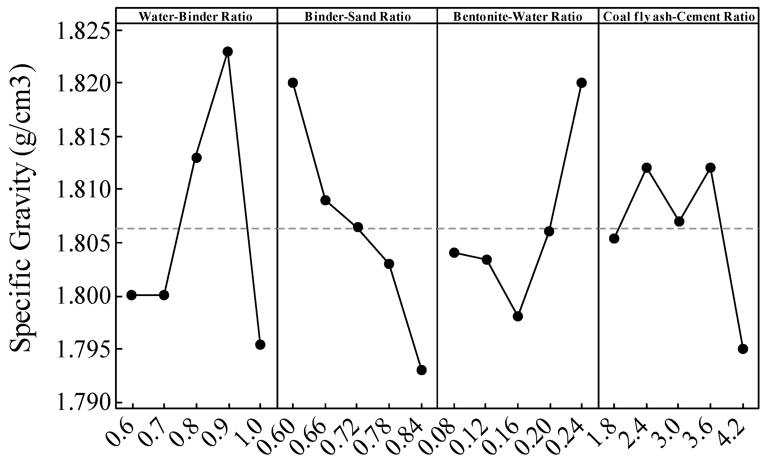
| Levels | Water–Binder Ratio | Binder–Sand Ratio | Bentonite–Water Ratio | Coal Fly Ash–Cement Ratio |
|---|---|---|---|---|
| Mean value 1 | 1.8 | 1.82 | 1.804 | 1.805 |
| Mean value 2 | 1.8 | 1.809 | 1.803 | 1.812 |
| Mean value 3 | 1.813 | 1.806 | 1.798 | 1.807 |
| Mean value 4 | 1.823 | 1.803 | 1.806 | 1.812 |
| Mean value 5 | 1.795 | 1.793 | 1.82 | 1.795 |
| Range | 0.028 | 0.027 | 0.022 | 0.017 |
| Sort | 1 | 2 | 3 | 4 |
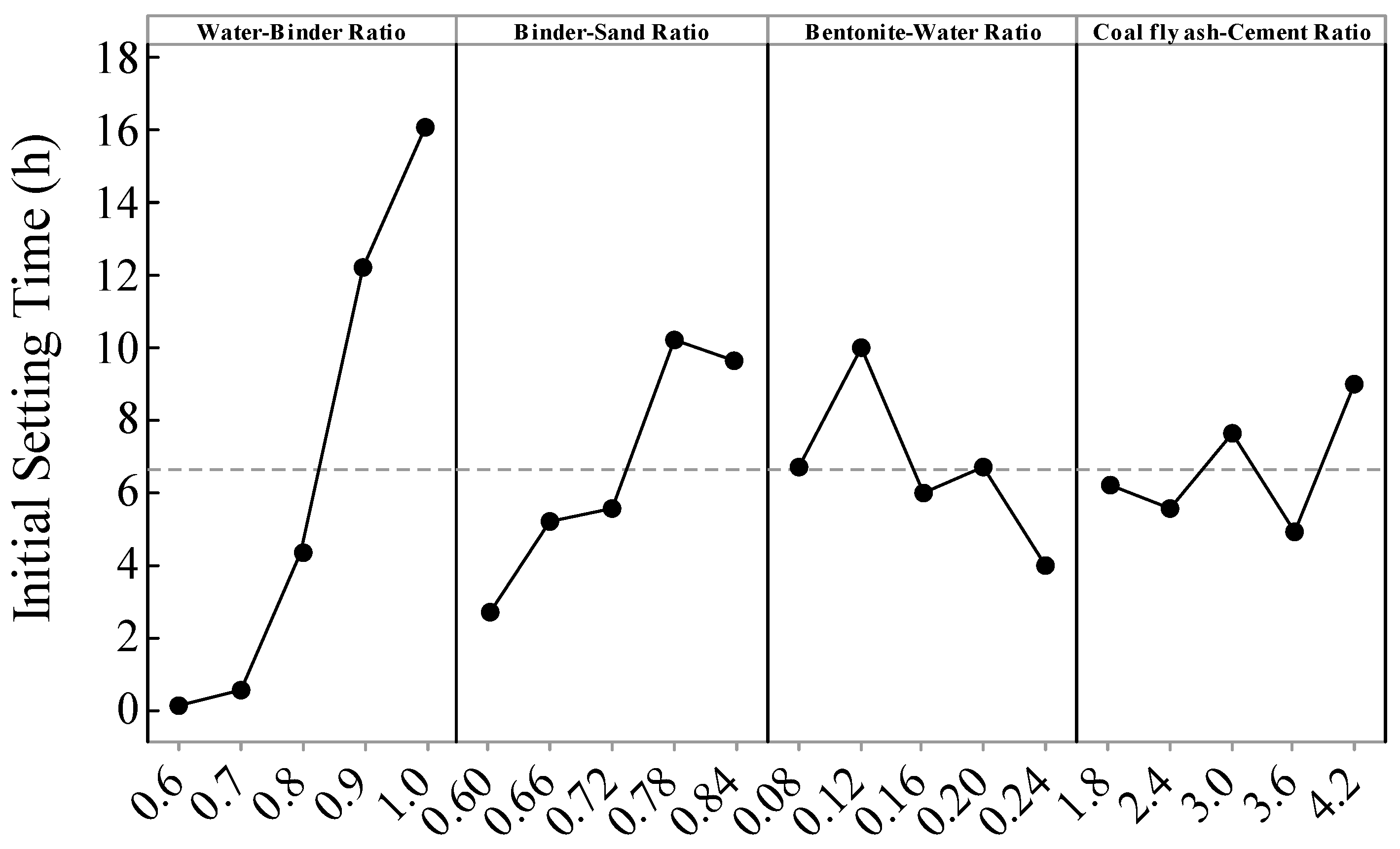
| Levels | Water–Binder Ratio | Binder–Sand Ratio | Bentonite–Water Ratio | Coal Fly Ash—Cement Ratio |
|---|---|---|---|---|
| Mean value 1 | 0.1 | 2.68 | 6.636 | 6.174 |
| Mean value 2 | 0.506 | 5.178 | 9.99 | 5.498 |
| Mean value 3 | 4.29 | 5.49 | 5.916 | 7.626 |
| Mean value 4 | 12.154 | 10.168 | 6.66 | 4.858 |
| Mean value 5 | 16.072 | 9.606 | 3.92 | 8.966 |
| Range | 15.972 | 7.488 | 6.07 | 4.108 |
| Sort | 1 | 2 | 3 | 4 |
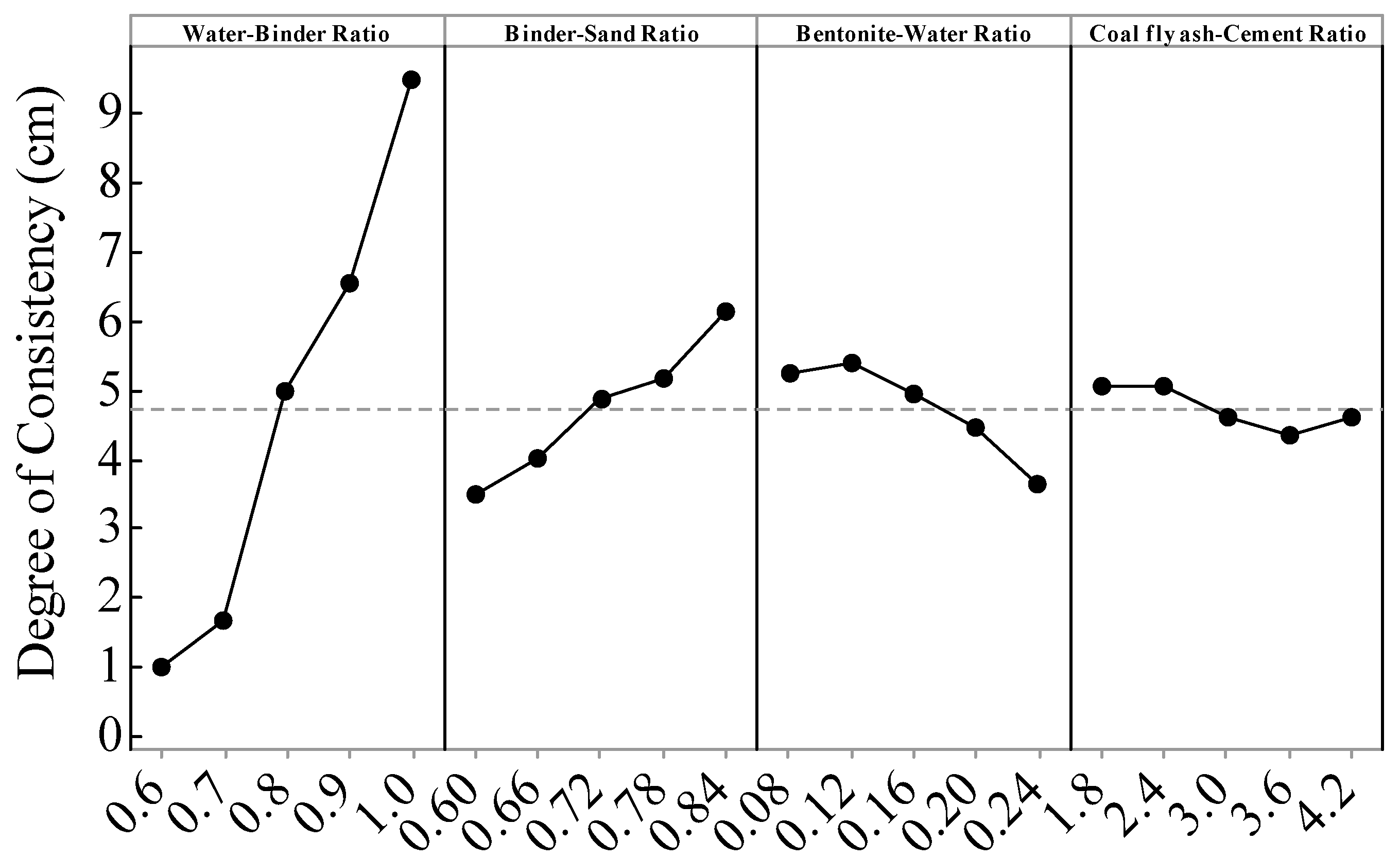
| Levels | Water–Binder Ratio | Binder–Sand Ratio | Bentonite–Water Ratio | Coal Fly Ash–Cement Ratio |
|---|---|---|---|---|
| Mean value 1 | 1 | 3.47 | 5.23 | 5.06 |
| Mean value 2 | 1.64 | 4.01 | 5.38 | 5.04 |
| Mean value 3 | 4.96 | 4.87 | 4.95 | 4.59 |
| Mean value 4 | 6.56 | 5.17 | 4.45 | 4.36 |
| Mean value 5 | 9.48 | 6.12 | 3.63 | 4.59 |
| Range | 8.48 | 2.65 | 1.75 | 0.7 |
| Sort | 1 | 2 | 3 | 4 |
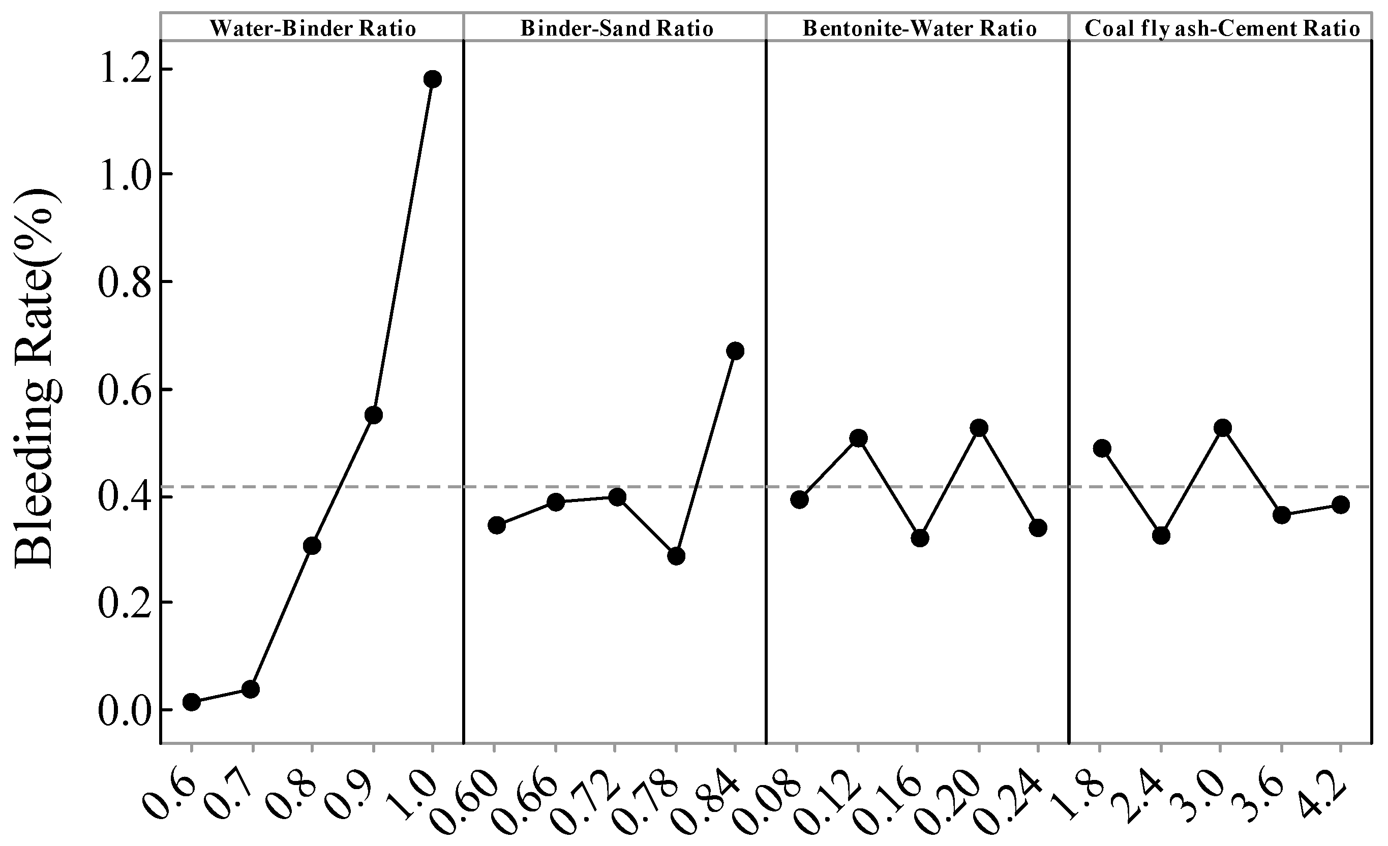
| Levels | Water–Binder Ratio | Binder–Sand Ratio | Bentonite–Water Ratio | Coal Fly Ash–Cement Ratio |
|---|---|---|---|---|
| Mean value 1 | 0.01 | 0.342 | 0.392 | 0.486 |
| Mean value 2 | 0.038 | 0.388 | 0.508 | 0.322 |
| Mean value 3 | 0.304 | 0.396 | 0.318 | 0.528 |
| Mean value 4 | 0.55 | 0.286 | 0.526 | 0.362 |
| Mean value 5 | 1.18 | 0.67 | 0.338 | 0.384 |
| Range | 1.17 | 0.384 | 0.208 | 0.206 |
| Sort | 1 | 2 | 3 | 4 |
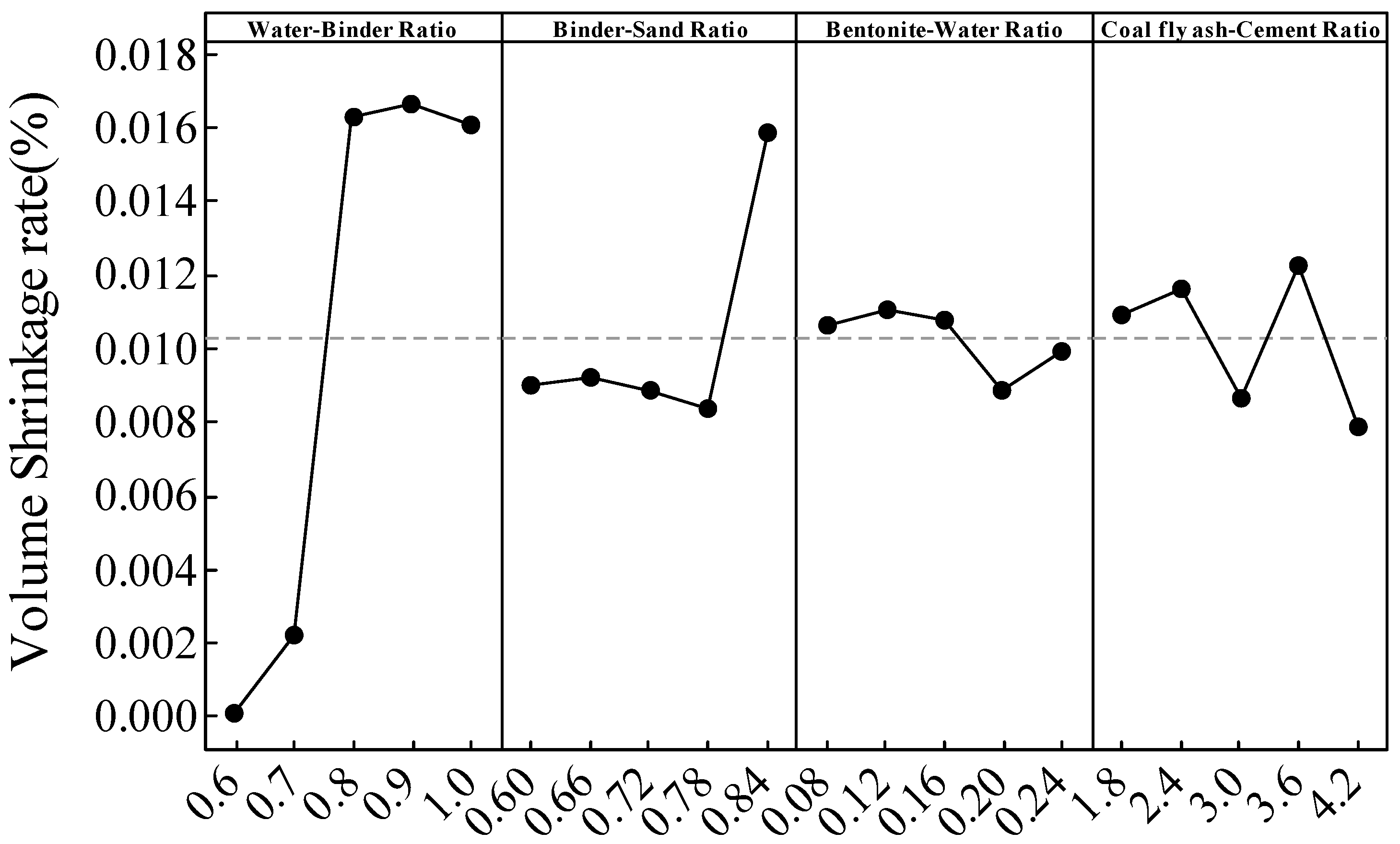
| Levels | Water–Binder Ratio | Binder–Sand Ratio | Bentonite–Water Ratio | Coal Fly Ash–Cement Ratio |
|---|---|---|---|---|
| Mean value 1 | 0.0001 | 0.00904 | 0.01066 | 0.01092 |
| Mean value 2 | 0.00222 | 0.0092 | 0.0111 | 0.0116 |
| Mean value 3 | 0.01628 | 0.00886 | 0.0108 | 0.00866 |
| Mean value 4 | 0.01666 | 0.00838 | 0.00884 | 0.0123 |
| Mean value 5 | 0.01608 | 0.01586 | 0.00994 | 0.00786 |
| Range | 0.01656 | 0.00748 | 0.00226 | 0.00444 |
| Sort | 1 | 2 | 4 | 3 |
Publisher’s Note: MDPI stays neutral with regard to jurisdictional claims in published maps and institutional affiliations. |
© 2022 by the authors. Licensee MDPI, Basel, Switzerland. This article is an open access article distributed under the terms and conditions of the Creative Commons Attribution (CC BY) license (https://creativecommons.org/licenses/by/4.0/).
Share and Cite
Ou, Y.; Tian, G.; Chen, J.; Chen, G.; Chen, X.; Li, H.; Liu, B.; Huang, T.; Qiang, M.; Satyanaga, A.; et al. Feasibility Studies on the Utilization of Recycled Slag in Grouting Material for Tunneling Engineering. Sustainability 2022, 14, 11013. https://doi.org/10.3390/su141711013
Ou Y, Tian G, Chen J, Chen G, Chen X, Li H, Liu B, Huang T, Qiang M, Satyanaga A, et al. Feasibility Studies on the Utilization of Recycled Slag in Grouting Material for Tunneling Engineering. Sustainability. 2022; 14(17):11013. https://doi.org/10.3390/su141711013
Chicago/Turabian StyleOu, Yazhou, Gang Tian, Junjie Chen, Guoguang Chen, Xiaoyu Chen, Hai Li, Binggang Liu, Tianyu Huang, Mengyun Qiang, Alfrendo Satyanaga, and et al. 2022. "Feasibility Studies on the Utilization of Recycled Slag in Grouting Material for Tunneling Engineering" Sustainability 14, no. 17: 11013. https://doi.org/10.3390/su141711013