MSP430 Real World Current in Low Power Modes

I have been having some fun trying to minimize the current required for a battery powered application using an MSP430FR2433. I chose the MSP430 since it has a stellar reputation for low power, I really like the orthogonal instruction set, any MSP430 launchpad board can program and debug them, and they seem to have more availability right now than other similar low power MCUs.

There seem to be very few published real world measurements of the current used in the low power modes for this series of MCUs. I ran some quick tests to show the current draw at 3.3V in LPM3, LPM4, LPM3.5, and LPM4.5 with and without the RTC using the VLO and with and without the SVS enabled. All measurements were completed with a calibrated Fluke 87V that has a resolution down to 100nA.

Power ModeCurrent (uA)
LPM3 with SVS and RTC using VLO17.4
LPM3 with SVS, no RTC17.2
LPM3 no SVS, no RTC17.1
LPM4 with SVS0.6
LPM4 no SVS0.4
LPM3.5 with SVS and RTC using VLO0.4
LPM3.5 with RTC using VLO, no SVS0.2
LPM4.5 with SVS0.2
LPM4.5 no SVS<0.1

ACLK uses REFO and stays active in LPM3, thus why LPM3 shows considerably higher current than LPM4. Using XT1 for ACLK should drastically reduce the LPM3 current. I plan on testing this at some point.

LPM3.5 and LPM4.5 shut down the voltage regulator, losing all RAM and register contents. The application must initialize the complete device after a wakeup from these modes. However, the inclusion of backup memory and FRAM on this MSP430 allows one to easily save state and restore it on reset. This makes these modes quite useful in practice.

Operating mostly in a low power mode using a 235mAh CR2023 allows for some impressive runtime using this MCU.
Power Wheels Rebuild – Traction Control, Fixed Point Math, and DC Motor Constants

My daughter has been using her highly modified power wheels style car for quite a while now and I decided that a few issues needed to be fixed:

  • Running the motors in parallel means that one motor could be damaged by using a majority of current in certain situations
  • It is too easy to make the driven wheels spin out on wet surfaces or when trying to go over obstacles
  • My wife thinks the car is much too fast at times and needs to be slowed down

New Control Board

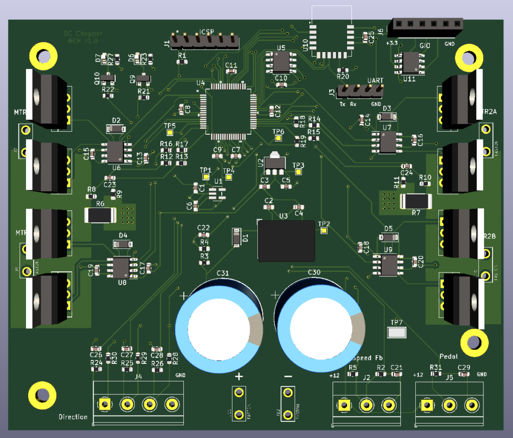
3D Circuit Board Layout

I designed a new control board to independently control each motor. This allows me to finely control the speed and torque of each motor separately.

Continue reading

Power Wheels DC Chopper Upgrade

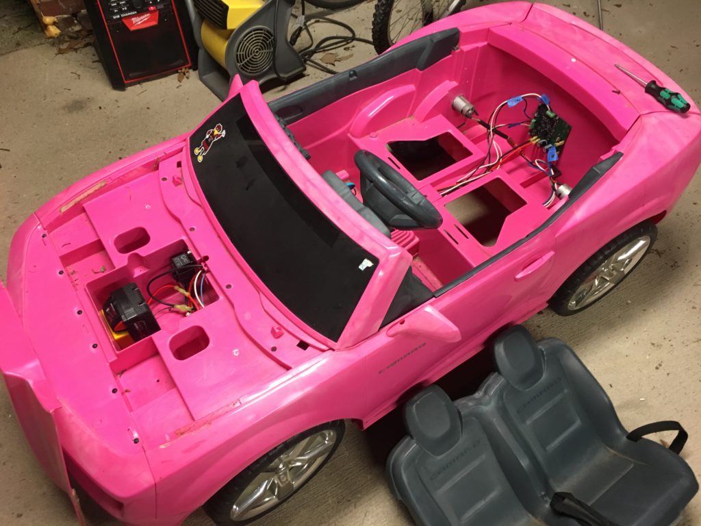
Upgraded Camaro Overview Picture

Walking through my neighborhood one day, I happened upon a pink Camaro Power Wheels style kids riding toy that someone was throwing away. It appeared to have been left outside for an extended period of time and was full of ants! I guessed that the car stopped working, probably due to being full of ants, and they decided to toss it rather than try to clean it up.

I have a young daughter at home that I knew would just love a pink convertible Camaro, so I grabbed it and decided to get it working for her.

The first thing I did was to rip out all of the wiring and switches. The entire setup was extremely simple. The car was powered by two small DC motors, one for each rear wheel. The motors look to be standard 550 size and were geared down quite a bit with plastic gearboxes. The shifting mechanism was two integrated switches that allowed for full speed forward, half speed forward, and reverse. The biggest surprise was that the foot pedal was simply a switch and did not allow for any sort of variable speed control! All of this was connected to a standard 12V lead acid battery.

Continue reading

In Defense of 8-Bit

A while back I was asked to work on a project that required a microcontroller to monitor a signal that determined the health of a system. The microcontroller had to fit in a tiny area and handle extreme temperature ranges. The signal to monitor was a series of pulses that had to stay within a certain time period. This is the sort of thing that any microcontroller should be able to handle very easily, assuming it could fit where I needed it and work at the temperatures required.

Continue reading

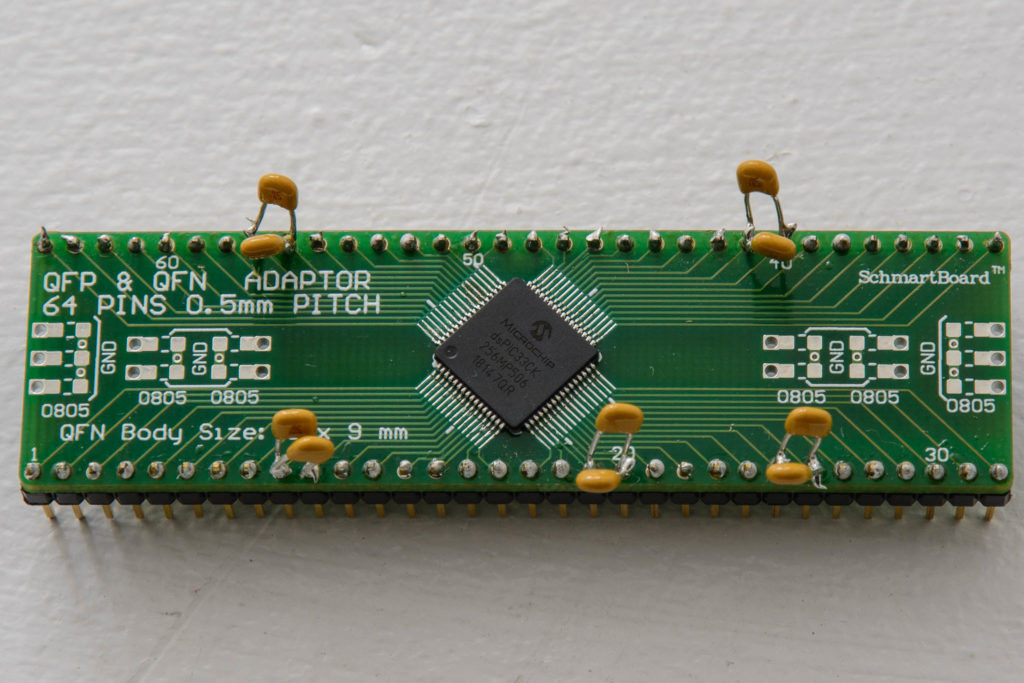
Startup Without Peripheral Libraries – dsPIC33CK

Startup without peripheral libraries series

The dsPIC is one of the easier MCUs in this series to get running.  Much like the PIC32MK, the default startup scripts are hidden in the compiler directory and included by default.  Generally, they do not need to be touched.  Almost all of the register definitions are included the standard device header file xc.h.  This provides the register values both as a full register variable and as a bit fields.  The compiler contains some built in functions that are required to switch clocks.  These functions are documented in the compiler reference.

This example uses the internal 8MHz fast oscillator and PLL to run the system clock at 180MHz.  I then set up Timer 1 and interrupts.

The steps are as follows:

Continue reading

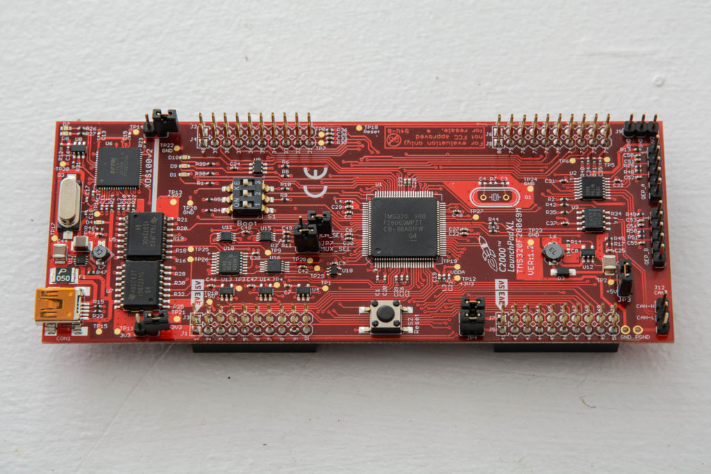
Startup Without Peripheral Libraries – TMS320F28069

Startup without peripheral libraries series

The TI C2000 series of MCUs are not designed for people new to development.  TI does not have any software that auto-configures the devices, the startup code does not automatically populate things like vectored interrupt tables, and register defaults require configuration.  However, TI does provide an extensive set of generic hardware configuration files and peripheral example files for every peripheral that are clean and concise.  I like this much better than any configuration utility.  The best way to get started is to download C2000Ware.

I will be using some of the files from C2000Ware in this example:

Continue reading

Startup Without Peripheral Libraries – PIC32MK

Startup without peripheral libraries series

Microchip MPLAB X hides some of the details of starting up the PIC32.  The default startup code and linker scripts are hidden in the compiler directory and included by default.  Generally, they do not need to be touched.  Almost all of the register definitions are included the standard device header file xc.h.  This provides the register values both as a full register variable and as a bit fields.  The bit fields are a really nice touch that Microchip does with all their PIC MCUs.  I also include cp0defs.h to access the defines used to configure CP0.

This example uses the built in 8MHz fast RC internal oscillator and PLL to run at 120MHz.  I then set up Timer1 and enable interrupts.

The startup works as follows:

Continue reading

Startup Without Peripheral Libraries – STM32

Startup without peripheral libraries series

A default bit of basic startup code is created when you start a project in Atollic TrueSTUDIO.  For my project, the code is called startup_stm32f446xx.s.  This code sets up the initial vector table, the program counter, the stack pointer, and branches to the main function.  I also include the standard device header files that ST provides and use the definitions in the files for register configuration.  These are well documented in the headers and the names match the datasheet.

This configuration uses the 16MHz internal oscillator and PLL to run the system clock at 180MHz.  I then set up the SysTick timer for a 1ms interrupt.

The rest of the startup code is pretty straightforward:

Continue reading

Startup Without Peripheral Libraries

Almost all microcontroller manufacturers provide peripheral libraries that are intended to make development using their products faster and easier.  In some instances, these libraries work well and really accelerate development.  On the other hand, some libraries contain bugs, only cover a subset of the peripheral features, add huge amounts of overhead, or require so much research and exploration that you might as well just use the reference guides and program the registers yourself.

I generally only use the manufacturer provided peripheral libraries for items that are very complex such as USB and Ethernet.  Instead, I read the references and program the registers myself.  I have discovered that once you start doing more complex things with your chosen MCU, sooner or later you need to understand the peripherals on the register level.  The best way for me to do this is to simply start out using the registers.

Whether you use your own peripheral code or the libraries, you need to be comfortable with what they are doing and verify that it matches the documentation as you understand it.

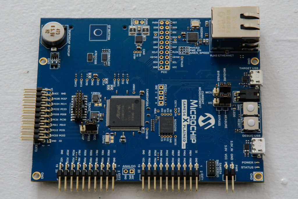
In my motor control microcontroller performance comparison post, I used a selection of different MCUs.  This series of posts is intended to cover how I got them working using only the bare minimum of libraries.

I will cover the following processors.  However, the basic code should work for all variations in the same family: