
A Systematic Review of Carbon Capture, Utilization and Storage: Status, Progress and Challenges

1
Petroleum Engineering School, Southwest Petroleum University, Chengdu 610500, China
2
New Energy Business Department, PetroChina Southwest Oil & Gas Field Company, Chengdu 646002, China
*
Author to whom correspondence should be addressed.
Energies 2023, 16(6), 2865; https://doi.org/10.3390/en16062865
Submission received: 13 February 2023
/
Revised: 15 March 2023
/
Accepted: 17 March 2023
/
Published: 20 March 2023
(This article belongs to the Special Issue Technological Innovation, Economic Analysis, and Environment Impact for Energy Production and Utilization)
Abstract
:The problem of global warming and climate change has attracted global attention, and reducing the concentration of CO2 in the atmosphere is an important step towards solving the problem. This paper mainly introduces the current development status, research hotspots, challenges and some emerging technologies of carbon capture, utilization and storage (CCUS). Among CO2 capture technologies, solvent absorption technology is currently the most mature and widely used technology, among which ionic liquid technology has great application prospects because its molecular structure can be designed and different functional groups can be connected. The surface functionalization of metal–organic frameworks in the adsorption method endows them with excellent CO2 adsorption capacity. In CO2 transportation, temperature and pressure must be considered in pipeline transportation, because they will affect the phase state of CO2 transportation. The impact of impurities on CO2 pipeline transportation is a challenge that affects pipeline design and transportation safety. In CO2 utilization, the key to enhanced oil recovery, gas recovery and displacement of coalbed methane is to increase the recovery rate and increase the storage capacity at the same time. Only by strengthening the research on the adsorption behavior between CO2 and CH4 and revealing the relevant mechanism can innovative technologies be developed. The chemical utilization of CO2 has formed many routes, but they all lack certain advantages. Most scholars are working on catalysts for CO2 conversion, especially copper-based catalysts that can convert CO2 into methanol. The conversion rate of CO2 can be effectively increased through doping or process improvement. The coupling of electrocatalytic technology and renewable energy is an important development direction in the future. In CO2 storage, geological storage is currently the most important method, especially in saline aquifers. There are currently critical issues concerning reservoir integrity and leakage potential that should be further investigated. CO2 leakage will cause serious environmental problems, and the common monitoring methods are reviewed and discussed in this paper. Finally, the research status, hotspots and cooperation networks of CCUS are summarized by using CiteSpace software in order to help the development of CCUS technology. In addition, through the review and analysis, it is found that CCUS is faced with challenges such as low capture efficiency, difficulties in transformation and utilization, high operating costs, lack of strong support policies, and lack of international cooperation, which restrict the further development of CCUS.
1. Introduction
In the past few decades, due to human activities such as fossil fuel power generation, more and more CO2 in the atmosphere has been caused, and the greenhouse effect has become more and more obvious. This poses a huge threat to human and global security. At present, the CO2 concentration in the atmosphere has exceeded 400 ppm, which is about 40% higher than before industrialization, and the surface temperature has increased by about 0.8 °C [1]. However, it is almost impossible to replace conventional power plants with clean energy power generation in the short term. Moreover, the International Energy Agency reported that although affected by the COVID-19, global carbon emissions have plummeted. However, it is expected that with the gradual improvement of the epidemic situation in various countries, carbon emissions will rise further, and there is no sign that peak carbon emissions have yet been reached. In this case, to achieve the goal of controlling the temperature rise to 2 °C, we must accelerate the transformation of the energy system. In addition to vigorously developing new energy sources, carbon capture, utilization and storage (CCUS) technology has also attracted the attention of the academic community. This is an emerging technology with the potential to reduce CO2 emissions on a large scale. It is considered to be the key technology for mitigating climate change and has attracted great attention from governments, industry and academia in recent years. As shown in Figure 1, CCUS technology refers to the selective removal of CO2 from the air flow of emission sources (power plants, steel plants and cement plants) by using capture systems, and then the CO2 is transported to the storage site through pipelines for storage or utilization in the plant. CCUS can help better manage CO2 concentrations.
The development level of CO2 capture technology is the key to the whole CCUS technology. It mainly uses methods such as solvent absorption, solid adsorption, membrane separation and low-temperature separation to separate CO2 in the mixed gas from other components. CO2 transport plays a connecting role in CCUS technology, which connects carbon capture with storage and utilization. It can ensure the safe and economical operation of the CCUS system. Pipeline transportation is the most common mode of transportation. The cost of transporting one ton of CO2 is 1–10 USD/km. The demand for CO2 pipeline construction will increase significantly in the future. The utilization of CO2 has attracted extensive attention. It is currently mainly used for enhanced oil and gas recovery, but people are paying more attention to other utilization methods of CO2, including chemical industry raw materials, mineralization, biological utilization and the food industry. People have developed a variety of conversion routes and methods to convert CO2 into chemicals, but most of them are in the pilot stage, mainly because of the high conversion cost and low conversion efficiency. The amount of CO2 used every year is very small, which is far lower than the emission of CO2. Moreover, the used CO2 will be re-released at the end of the product life cycle. But its importance lies in the indirect reduction of CO2 emissions by avoiding the use of fossil carbon. In the future, if we want to achieve the goal of carbon neutrality, CO2 storage will still be the main strategy. CO2 storage can be divided into geological storage and ocean storage. Geological storage is the most common form of storage, especially in saline aquifers. It sequesters CO2 from the atmosphere, and over time the CO2 is converted into carbonate minerals for permanent storage.
CCUS technology has achieved remarkable development in recent years. It can ensure large-scale low-carbon utilization of fossil energy. It is a necessary solution for the decarbonization of industries that are having difficulty reducing emissions. There are more than 30 CCUS programs in operation around the world. Among them, North America is dominated by CO2 flooding. In Europe, ocean storage of CO2 is the main focus. Most of these commercially operated projects use chemical absorption technology or physical absorption technology to capture CO2 and use pipeline transportation or ship transportation technology to transport it. At present, relevant research on CCUS is constantly increasing, but most of them are focused on one side, as shown in Table 1, and few articles can systematically and comprehensively review various techniques in CCUS. A detailed review of various technologies in CCUS will help people better understand CCUS technology and help in its development. In addition, CCUS also faces many challenges in each link, which restricts the implementation of CCUS projects. By analyzing the existing problems and challenges of CCUS technology, this paper points out the future development direction of CCUS technology.
In this review, we followed the following steps: First, we used keywords such as CCUS, CO2 capture, CO2 transportation, CO2 utilization and CO2 storage to search the Web of Science core database. The search content does not include books and core papers, and the period covered is 2006–2021. Then, by simply reading the abstract, we screened the relevant literature. In this step, we screened 558 pieces of literature. Finally, we further screened the downloaded literature by careful reading and reduced the number to 265 articles. The screening criteria were to see whether they are closely related to the theme of this review. Finally, this paper will examine CCUS technology in detail through four parts: CO2 capture, CO2 transport, CO2 utilization and CO2 storage based on the 265 articles. This paper mainly introduces the current development status, research hotspots, challenges and some emerging technologies of CCUS technology. At the same time, CiteSpace software is used to measure and analyze these documents and analyze the research status, trends and cooperation.
2. CO2 Capture
According to the combustion process of fossil fuels and the technical basis of the CO2 capture system, carbon capture can be simply divided into three processes: post-combustion capture, pre-combustion capture and oxyfuel combustion capture. Post-combustion capture mainly refers to the capture of CO2 from the waste gas produced by the combustion of fossil fuels or other carbon-containing fuels. It is currently the most widely used carbon capture strategy. Its technology is currently highly mature and has a large number of commercial applications [12]. Compared with pre-combustion capture and oxyfuel combustion capture, it has several advantages, for example, the transformation of CO2 emission sources is small, it can be quickly applied to existing power plants, and the later maintenance cost is small. It also has a small impact on production activities and high flexibility [13]. Of course, the carbon capture efficiency is low due to the low content of CO2 in the gas after combustion [14]. At the same time, the separation effect will also be affected because the gas after combustion contains other impurities. In conclusion, post- combustion capture technology needs to develop efficient and ideal adsorption materials, and improve the energy efficiency of post-combustion carbon capture equipment. At present, most research focuses on post-combustion capture strategy [15]. Common capture technologies are shown in Figure 2, which will be described in detail below.
2.1. Solvent Absorption Technology
Solvent absorption technology is the most widely used CO2 capture technology at present, which is mainly used for post-combustion capture and pre-combustion capture. Due to its good separation effect, low application cost and relatively mature technology, it is the key technology to implement the “Zero Emissions Energy Strategy”. In this article, we will divide solvent absorption into the physical absorption method, chemical absorption method and the physical–chemical absorption method according to whether physical and chemical reactions occur in the process of solvent absorption. In addition, since the current research focus has been extended to the use of solvent mixtures, we will also discuss them in this article.
2.1.1. Chemical Absorption Technology
Chemical absorption technology mainly uses a liquid solution to absorb CO2 through a chemical reaction, and the absorbed CO2 is released for storage or utilization through reverse decomposition. Typical CO2 chemical absorption technology is shown in Figure 3, which mainly relies on the absorption tower to remove CO2 in the flue gas, and relies on the stripping tower to desorb and regenerate [16].
In chemical absorption technology, commonly used solvents mainly include ammonia, potassium carbonate, amino solvent and alkaline solvent [17]. Among them, amino solvents are considered to be the most developed among the currently studied solvents and are widely used in post-combustion carbon capture (PCC). Its disadvantage is that the amine is easily degraded during long-term operation, and its capture property is reduced [18]. It has the advantages of high chemical reactivity with CO2, low production cost and large-scale stable operation [19]. Ammonia aqueous solution is superior to conventional ammonia solution in CO2 capture, so it is a good substitute. However, due to its high volatility, it will escape into the airflow, so there are still technical obstacles [16].
Chemical absorption technology has some applications, but there are still some problems to be solved. For example, compared with solid adsorption technology, its energy consumption is high, compared with physical absorption technology, its efficiency is low, the absorbent suffers evaporation loss and oxidative degradation, and the absorbent will cause corrosion to equipment, etc. In practical application, the negative effects of SOx, NOx and oxygen on absorbents should also be considered in developing more appropriate models [20]. In order to overcome these shortcomings, many scholars began to study some additives and mixtures (such as piperazine (PZ) and PZ derivatives). Reducing the energy consumption of chemical absorption technology is an important research direction for the future. Energy consumption can be effectively reduced by process improvement (heat integration strategy) or by using solvents with high heat absorption.
2.1.2. Physical Absorption Technology
Physical absorption technology can be applied when CO2 and liquid solvents do not undergo obvious chemical reactions, and its operation is based on Henry’s Law [20]. Physical absorption is suitable for use under high pressure and low temperature so that the solubility of the gas in a liquid solvent will be greater [16]. The physical absorption method has a simple process, high operating pressure, and can capture some other harmful gases, but the recovery rate of CO2 is low, which is usually applied to situations where the requirements for gas purification are not high.
Physical absorption methods usually include the propylene carbonate method, the polyglycol dimethyl ether method and the low-temperature methanol washing method. Different physical absorption methods have different advantages and disadvantages, see Table 2 for their comparison. Physical solvent has good application in integrated gasification combined cycle (IGCC) power generation facilities, with high capture efficiency and low energy loss [16,21].
Chemical absorption technology and physical absorption technology have different advantages and disadvantages. Chemical absorption technology is suitable for absorbing CO2 at low pressure, and physical absorption technology applies to absorbing CO2 at high pressure. In chemical absorption technology, due to the chemical reaction between CO2 and solvent molecules in forming chemical bonds, it is highly selective to CO2. In physical absorption, although there is a weak interaction between CO2 and solvent, its regeneration energy is low [22]. Therefore, is there a method that can combine the advantages of these two methods? For this reason, people began to study solvent-mixing technology.
2.1.3. Solvent Mixed Absorption Technology
Single solvent systems have been deeply studied, and many properties of solvents have been defined. At present, the research focus has been on the research and development of solvent mixtures, which can be developed by mixing various solvents and synergistic effects with accelerants. At present, promising solvent mixtures include amine-based blends, NH3-based blends, K2CO3-based blends and deep eutectic solvents. These blends mainly combine the advantages of different solvents. For example, ethanolamine sulfolane water is an amino blend, which combines physical and chemical solvents, and has the advantages of both methods. Alcohol amine is a chemical solvent, which can absorb organic sulfur in the mixed gas and can also dissolve part of H2S and CO2. Sulfolane is a physical solvent, which can absorb CO2 in the mixture. This solvent has a wide application range, low CO2 content in purified gas and low corrosivity [22]. The mixture of MEA + MDEA is a typical synergistic effect. The reaction rate is increased by adding MEA, and the regeneration energy is reduced by adding MDEA.
Deep eutectic solvent is a new green solvent developed to overcome the high price and toxicity of traditional ionic solvents. Usually, two components are mixed according to a certain molar ratio, and the melting point of the eutectic solvent formed is usually lower than that of each component. Deep eutectic solvents have many advantages, such as low price, easy degradation, and little environmental pollution, and are suitable for large-scale preparation [18,23]. The most common deep eutectic solvent is a combination of quaternary ammonium halide and hydrogen bond donor [24,25]. At present, the research and development of deep eutectic solvents are still in the initial state. Although much progress has been made, there is still some distance to go before large-scale commercial use.
2.1.4. Ionic Liquid Absorption Technology
An ionic liquid is a kind of “green solvent”, which has the advantages of wide operating pressure, low corrosion, and easy separation of products. The designability of its molecular structure creates opportunities for the design of ionic liquids. By connecting different functional groups, ionic liquids for different purposes can be obtained [26]. The common functional groups include amine, fluorine atom, hydroxyl, etc. The introduction of cation in an amino group is more effective, and ionic liquids with multiple amine sites usually have higher CO2 absorption capacity than ionic liquids with one primary amine group. Ionic liquids containing hydroxyl groups have good separation performance of CO2 at low pressure [27]. Xu [28] proved that the addition of super bases during the preparation of ionic liquids can effectively improve their ability to capture CO2.
Of course, in addition to the influence of functional groups, the length of the alkyl chain and the type of anion will affect the CO2 absorption capacity and viscosity of the ionic liquid [26,29]. Ionic liquids usually have high viscosity, especially those containing amino groups. This is usually due to the formation of hydrogen bonds in ionic liquids. The viscosity of ionic liquids can be reduced by introducing hydrogen receptors, or by mixing with organic solvents [27,30]. H2S and CH4 need to be separated before CO2 capture because they will reduce the solubility of CO2 and the selectivity of ionic liquids [31].
Although ionic liquids have great application prospects in CO2 capture, most of the current applications of ionic liquids are limited to laboratories. Ionic liquids are expensive and the production process is complex, which are the main factor hindering the large-scale application of ionic liquids [32]. In addition, the potential toxicity and non-degradability of ionic liquids also hinder the large-scale application of ionic liquids. Thermodynamic models of CO2 and ionic liquid systems also present challenges that require further study in the future.
2.2. Solid Adsorption Technology
The solid adsorption technology is mainly realized by the intermolecular attraction between the gas or liquid and the active point on the solid adsorbent. The adsorption of CO2 by an adsorbent is usually realized by physical adsorption or chemical adsorption [33]. Good adsorbent, regeneration process and adsorption cycle time are required in the adsorption process [34]. This paper will mainly discuss the research progress of solid adsorbents by reviewing: carbon-based adsorbents, porous materials and other adsorbents.
2.2.1. Carbon-Based Adsorbent
Carbon-based sorbents mainly refer to materials composed of carbon atoms, which are simple to prepare and low in cost. They are usually used to capture CO2 under high pressure because the adsorption capacity of CO2 usually increases with the increase of pressure. The amount, size and distribution of voids in carbon-based adsorbents play an important role in CO2 capture. By adding various functional groups on the surface of the carbon-based adsorbent, its carbon capture performance can be optimized [35]. In the carbon matrix, increasing the pH of some parts of the surface will change the charge distribution on the surface and enhance its adsorption capacity [36]. The interaction between carbon-based adsorbents and CO2 is very weak, so this presents a challenge for the selectivity and capacity of carbon-based adsorbents, especially at high temperatures and low partial pressures. Common carbon-based adsorbents include biochar, activated carbon and graphene-based adsorbents.
Biochar has a high specific surface area, micropore, porosity and various functional groups. Its structure and surface properties determine that it is an excellent CO2 adsorbent. Biochar is an environmentally friendly and economical material [34,37,38,39,40]. Activated carbon is a kind of widely used carbon-based adsorbent. Its adsorption capacity is lower than that of zeolite or molecular sieve, and it will decrease significantly with the increase in temperature [33,41]. Activated carbon raw materials have a wide range of sources, with a wide range of pore size distribution and pore structure, and its manufacturing cost also has huge advantages [42]. Activated carbon produced by biomass containing heteroatoms (Such as O, S, P and N) can better absorb CO2 [43]. Activated carbon can be divided into physical activated carbon and chemical activated carbon according to the activation mode. Different reaction conditions and activated chemicals will affect the physical and chemical properties of activated carbon, such as specific surface area, surface functional groups, shape, etc. [44,45,46,47,48,49]. Future research work on activated carbon will focus on improving its adsorption capacity and selectivity at low CO2 partial pressure and producing adsorbents with adjustable active surface area and pore size. Graphene-based adsorbent is a carbon nano material, because its two-dimensional and hexagonal-filled lattice structure is similar to a honeycomb single carbon layer, and the active functional groups on the surface make it have good physical and chemical properties [50,51,52,53]. Graphene has a poor CO2 adsorption effect, and its adsorption performance can be enhanced through activation, because activation can make graphene produce a three-dimensional structure, giving it a large surface area [54]. At present, the most effective graphene-based adsorbent is PANI/HEG (polyaniline/hydrogen exfoliated graphene), which has good cycle performance [55]. Future research on graphene is mainly aimed at improving its CO2 adsorption capacity by attaching different functional groups and heteroatoms to its surface.
2.2.2. Porous Material
At present, many porous materials are widely studied for carbon capture. Porous materials have the advantages of high absorption efficiency and large adsorption capacity. The pore diameter, geometric shape and specific surface area of porous materials will affect the CO2 capture effect. The commonly used porous materials include zeolites, metal–organic frameworks (MOFs) and mesoporous materials.
MOFs are emerging crystalline porous materials, which have the advantages of high pore volume, structural diversity, easily adjustable pore structure and surface functionalization [56,57]. MOFs are widely used in gas storage, drug delivery and heterogeneous catalysis, but their application in the selective adsorption of gas is one of the most active research fields at present [41]. MOFs can be functionalized by different methods to improve their CO2 adsorption capacity. Common methods include adding polar functional groups, opening metal sites and modifying with Lewis basic sites [41,56,58]. These methods can better exploit the tailorability of MOFs, making them possess excellent CO2 adsorption capacity. However, the cost of production and utilization of MOFs is too high at present, so it is difficult to use them on a large scale. In addition, the synthesis process of MOFs will cause environmental pollution, which also limits its application. In the future, reducing its synthesis cost and environmental pollution during the synthesis process are the main research directions.
Zeolite is a porous crystalline material composed of aluminosilicates, and most zeolites for CO2 capture are synthetic. Synthetic zeolite can control its porosity and crystallinity in the process of synthesis, so it has more advantages than natural zeolite in capturing CO2. The zeolite frame is of a microporous structure, and its pore size can be adjusted, so the zeolite for CO2 adsorption can be customized [59]. When most zeolites encounter water molecules, their CO2 capture performance will decline. However, the hydrophobicity of zeolites with a higher silicon–aluminum ratio will be enhanced, and the hydrophobicity can also be increased by introducing hydrophobic functional groups [60]. Although synthetic zeolite has good trapping performance, its application is restricted by its high synthetic cost and environmental pollution.
During the past decade, mesoporous materials have become favorable candidates for CO2 capture materials. Common mesoporous materials include mesoporous silica and mesoporous metal oxides. Silica is one of the most abundant substances in the world. Mesoporous silica is usually prepared by the Stöber method, and its pore diameter and specific surface area can be easily adjusted [59]. Mesoporous silica is a CO2 adsorbent suitable for amine loading. The rich hydroxyl groups on the surface of silica are conducive to amine functionalization and improve its CO2 adsorption capacity [61]. Common mesoporous metal oxides include TiO2, MgO, alumina and cerium oxide [62,63,64] in which mesoporous ceria has the largest CO2 adsorption capacity. TiO2 can also quickly absorb CO2.
2.3. Membrane Separation Technology
Membrane separation technology can generally be divided into gas separation membrane and gas absorption membrane. The working principles of the two membranes are shown in Figure 4. The gas separation membrane (Figure 4a) is mainly used to separate gas by permeating one or more gases from one side of the membrane to the other side through the selectivity of the membrane. The driving force is the pressure difference of the gas to be separated on both sides of the membrane. The gas absorption membrane (Figure 4b) is mainly used to selectively absorb gas through a chemical absorption solution, and the membrane only serves to isolate gas and absorption solution.
Gas separation membranes can be divided into three categories: inorganic membranes, organic polymer membranes and mixed matrix membranes. The relationship between the selectivity and permeability of most polymer membranes is shown in Figure 5. The permeability of polymer membranes with high selectivity is generally poor. In order to solve this problem, people began to study mixed matrix membranes. Norahim et al. [66] discussed the influence of different fillers on composite membranes. For example, mixing carbon nanofibers with polysulfone can improve its selectivity and permeability. The dendriform mixed matrix membrane is composed of polyether block amide (PEBA), polyethylene glycol (PEG) and nano-X zeolite, its CO2 permeability and selectivity increase with the increase of feed pressure and PEG loading [67]. Some studies have shown that the addition of MOF can improve the performance of mixed matrix membranes in CO2/CH4 separation, but there are still challenges in its preparation, such as poor compatibility and defects in the membrane matrix [68]. In the future, the commercialization of membrane separation technology can be accelerated by strengthening the research on mixed matrix membranes.
The gas absorption membrane mainly relies on the selectivity of the absorption liquid to achieve the purpose of separating and absorbing CO2. Under ideal conditions, the gas absorption membrane operates in a non-wetting mode, so there should be only a gas phase in the membrane pore. In order to ensure that the liquid phase will not penetrate the membrane pores, microporous membranes made of highly hydrophobic polymers are usually used [65,69,70,71]. Improving the hydrophobicity of the membrane is the key to solving the problem of membrane wetting. The direct use of highly hydrophobic materials will increase the cost. Usually, a thin layer of such materials is coated on the cheaper membrane to reduce the cost. Another method is to improve the hydrophobicity of the membrane by changing the surface roughness and surface tension energy [72]. In addition to studying membrane materials, an in-depth understanding of wetting mechanisms related to membrane performance and operating conditions should also be gained.
Membrane separation technology can also be divided into promoted membranes and non-promoted membranes. The action mechanism of a non-promoted membrane mainly depends on the “solution diffusion” transport process. In addition to the “solution diffusion characteristics”, the transport promotion membrane also includes an active transport mechanism to improve the permeability and selectivity of membrane materials. Supported liquid membranes (SLMs) are the first kind of transport-promoting membranes developed. They are non-dispersive liquid membranes, which mainly fill the pores of porous materials with liquid through capillary force as a selective material. It is generally divided into two types: mobile carrier and fixed carrier [73]. When ionic liquids are used to fill the pores, ionic liquids are mobile carriers, usually called SILMs. The interaction between ionic liquids and carriers will affect the distribution and separation performance of ionic liquids on carrier pores. For example, SILMs with hydrophobic carriers are more stable than SILMs with hydrophilic carriers [74,75]. Ahmad et al [70]. found that the higher the content of the ionic liquid in the membrane, the lower its selectivity. When using nano porous or porous oxide as the base membrane, the selectivity and permeability of ionic liquids can be enhanced [76]. The fixed-position carrier membrane uses the inherent chemical reaction with the fixed position to “jump” CO2 from one fixed carrier to the next through the membrane during CO2 capture. The research and development of promoted membranes are helping to improve permeability and selectivity [77].
2.4. Other Technologies
2.4.1. Low-Temperature Separation Technology
Low-temperature separation technology is a green method, which uses the difference of relative volatility of each component in raw materials to separate each component by distillation [78]. Sreenivasulu et al. [79] compared several low-temperature separation methods and found that condensation rotary separation is the only feasible option, with less energy loss and higher CO2 separation yield. Belaissaoui et al. [80] studied the mixed membrane low-temperature process for CO2 capture after combustion. The results showed that when the imported CO2 concentration was 30%, compared with the single low-temperature method, the mixed process could effectively improve energy efficiency. Xu et al. [81] studied a cryogenic capture system to capture CO2 in the flue gas of an LNG power generation system. This system can make full use of the cold energy of LNG during gasification. The results show that if the flue gas temperature can be reduced to below −140 °C, the CO2 recovery rate can reach 90%. Song et al. [82] summarized the existing low-temperature CO2 capture technology and concluded that low-temperature separation technology is more competitive only when low-cost cold energy is available. Low-temperature separation technology is only suitable for high-concentration CO2 flow (above 90%), not for dilute CO2 flow. In the future, we should optimize the operation parameters and process of the low-temperature capture system and make full use of the cold energy of the remaining gas after capture [10].
2.4.2. Microalgae
Among photosynthetic organisms, microalgae capture CO2 through its photosynthesis, which is a potential and promising candidate organism for carbon capture. The photosynthetic rate of microalgae is higher than that of terrestrial plants. Its cell structure is simple, its growth rate is fast, and its environmental adaptability is strong. Therefore, CO2 biological fixation through microalgae is more effective than that of terrestrial plants. Meanwhile, algae have a carbon-enrichment mechanism that inhibits photorespiration [82,83]. Song et al. [84] summarized the existing absorption-microalgae composite CO2 capture technology and concluded that the absorption microalgae composite CO2 capture technology can overcome the shortcomings of traditional absorption and microalgae fixation, that is, the absorption technology has high energy consumption for regeneration and low CO2 solubility in microalgae solution. It is very promising to use microalgae to directly capture CO2 in the flue gas generated by fossil fuel power plants or steel plants. Thomas et al. [85] discussed four strategies for biological mitigation of CO2 in flue gas, and they concluded that it is the most economical to supply flue gas directly to the microalgae photobioreactor, but it is necessary to select appropriate microalgae species to withstand the composition and high temperature of flue gas. It is also found that directly injecting flue gas into the pond containing microalgae can increase biomass productivity by 30%, which may be due to the presence of supplementary nutrients in the flue gas, resulting in the fertilizer effect [86]. Of course, CO2 capture by microalgae also has disadvantages. It requires specific geological and geomorphic structures, expensive separation equipment, uncertainty and long-term leakage risk. Therefore, in order to apply the microalgae capture technology on a large scale, it will be necessary to develop carbon source treatment technologies with different chemical forms and distribution characteristics, improve the utilization rate of industrial waste gas and optimize the cultivation process [87].
2.4.3. Chemical Looping Combustion Technology
The basic principle of chemical looping combustion technology (CLC) is to decompose the traditional combustion of direct contact reaction between fuel and air into two gas-solid reactions with the help of an oxygen carrier. The fuel and air do not need to contact, and the oxygen in the air is transferred to the fuel by the oxygen carrier. The oxygen carrier is periodically oxidized and reduced with air and fuel. CLC technology is considered the most cost-effective CO2 capture technology with the least energy loss. Its flow chart is shown in Figure 6. Oxygen carriers are usually transition metal oxides, because they are easy to reduce and reoxidize, and are suitable for recycling between two reactors [88,89]. Sajen et al. [90] studied the mixture of transition metal oxides (Such as CuO) and manganese oxides in CLC and found that the mixed oxides showed good activity for the oxidation of syngas fuel. Adanez et al. [91] compared the carbon capture efficiency of in situ gasification chemical chain combustion process (iG–CLC) and oxygen uncoupling chemical chain process (CLOU) under different reactor temperatures and different coals. The results show that the carbon capture efficiency and combustion efficiency of CLOU are better than those of iG–CLC. Hu et al. [92] compared various commonly used oxygen carriers and concluded that calcium oxide is an ideal CO2 carrier material with low cost, non-toxic and renewable. Among many chemical chain combustion reactors, a fluidized bed reactor is considered to be the best choice for large-scale application of chemical chain combustion technology. The fluidized bed reactor provides high solid circulation, which makes the fuel fully contact with the oxygen carrier in the fuel reactor, providing sufficient oxidation and reduction time for the oxygen carrier [93].
2.4.4. Electrochemical Technology
Electrochemical technology mainly uses an electrochemical reaction to selectively separate CO2 from the mixture, absorb and release CO2 through electrolyte solution, and regenerate electrolytes with an ionic conductive membrane. This method can capture CO2 at atmospheric concentration levels, low pressure and low temperature, with low energy demand. Most electrochemical methods capture and recover CO2 by moving the pH value of the working solution between acidic and alkaline pH values [94]. Muroyama et al. [95] reviewed the research progress of electrochemical separation of CO2 and found that electrodialysis using liquid electrolytes to capture solution is the most intensively studied electrochemical method at present.
Fuel cells and their hybrid system are one of the effective technologies to reduce CO2 emissions, which have the advantages of being clean and efficient. A high-temperature fuel cell is an electrochemical device, which is usually composed of an electrolyte, anode and cathode. Common high-temperature fuel cells mainly include solid oxide fuel cells, molten carbonate fuel cells and direct carbon fuel cells. Wang et al. [96] compared and introduced these three fuel cells and their application prospects in carbon capture in detail. Although there are still many challenges in the application of high-temperature fuel cells (such as the need to scale up fuel cell modules, and the high cost and safety of fuel cells), high-temperature fuel cells are still an excellent strategy for CO2 emission reduction in power plants.
Zhang et al. [97] gave an overview of a new high-temperature electrochemical CO2 transfer membrane. They compared several membranes made of different materials and evaluated some CO2 capture reactors based on these membranes. At the same time, the concept of electrochemical CO2 capture and conversion film was successfully demonstrated on a laboratory scale. Bae et al. [98] modified a seawater battery system for desalination and carbon capture. As shown in Figure 7, the system is mainly composed of three compartments: desalination, sodium collection, and carbon capture. The compartments are separated by sodium ion superconducting ceramic membranes. By charging and discharging the system, sodium ions are transferred from the desalination compartment to the carbon capture compartment, and hydroxide (OH−) ions are formed in the carbon capture compartment at the same time, and the hydroxide (OH−) ions and Na+, Ca2+, Mg2+ React with CO2 introduced in the atmosphere to form metal carbonate, to achieve the purpose of capturing CO2. The biggest shortcoming of this system at present is that the reaction of chlorine analysis is relatively difficult, and silver foil is temporarily used as a collecting electrode.
3. CO2 Transport
After the CO2 is separated from the flue gas, it must be transported to a storage site for storage or a factory for processing and utilization. Regardless of the ultimate fate of CO2, a safe, reliable and economically viable CO2 transportation system is a key link in the realization of CCUS technology. At present, the main transportation methods of CO2 are tanker transportation, pipeline transportation and ship transportation. Different shipping methods are suitable for different shipping situations. Example: A power plant with a design life of more than 23 years that produces CO2 suitable for pipeline transportation. For some short cycles CO2 transportation, tanker transportation and ship transportation are more competitive [1]. The amount of CO2 and the distance between the way of CO2 capture and the storage location are critical to the choice of CO2 transport mode. In this section of the review, we will focus on pipeline transportation and ship transportation.
3.1. Pipeline Transportation Technology
Pipeline transportation is the most economical way to transport large quantities of CO2. At present, the length of global CO2 pipelines exceeds 8000 km, and most of these pipelines are located in the United States. However, this length is far from meeting the demand for CO2 pipeline transportation under the carbon-neutral target, and a large number of CO2 pipelines need to be built in the future. This section summarizes the research on CO2 pipeline transportation from three aspects: transportation status and process, pipeline design and flow assurance, and transportation safety and risk [99,100].
3.1.1. Conveying Status and Process
CO2 has low critical temperature and pressure and is prone to phase changes. Its transport forms include gas transport, liquid transport, dense phase transport and supercritical transport. When multi-phase flows in the pipeline, CO2 is easy to change phase and causes pipe cavitation, so CO2 is usually transported in single-phase. Similar to oil and gas pipelines, CO2 also needs to be supplied with pressure through a compressor or pump to meet the purpose of transmission. Through practice, it is found that gas transportation and liquid transportation are more suitable for short-distance pipelines, and dense phase transportation and supercritical transportation are more suitable for long-distance pipelines. Among them, supercritical transportation and dense phase transportation are more economical [101]. Figure 8 shows the process flow diagram of these four conveying modes.
Some scholars and institutions have conducted some research on CO2 pipeline transportation [102]. Zhang et al. [103] found that the low critical temperature (31.1 °C) of CO2 is an important feature, and the control system temperature and pressure directly determine the process design and pressure loss of the system. Under favorable climatic conditions, CO2 transport in the supercooled liquid state can significantly save energy. At the same time, they also found that CO2 has the largest safe transport distance. Lu et al. [104] determined the flow transmission range of different pipe diameters according to the phase change during the transportation of liquid CO2. Drescher et al. verified the ability of the Schlumberger flow assurance tool OLGA and SINTEF Energy Research’s in-house CFD tool to simulate the decompression behavior of a CO2 pipeline. Their simulation results are consistent with the experiment. However, OLGA and SINTEF deviate from the experimental results in terms of simulated temperature [105].
3.1.2. Pipeline Design and Flow Assurance
The efficient transmission of CO2 from source to sink requires the adequate design of the CO2 transportation pipelines. The length of the pipeline should be minimized when designing the pipeline. Longer pipelines also require larger diameters, which will increase the construction and operation costs of the pipeline. The pipe diameter should not be too small. The pipe diameter determines the transmission capacity. Too small a diameter will cause too high a CO2 flow rate, increasing pressure loss and corrosion of the pipe wall [106]. Therefore, the most reasonable pipe diameter is the minimum pipe diameter to meet the CO2 transmission requirements [107]. Mohammadi et al. [108] proposed a cost optimization framework for a CO2 transportation system and concluded that pipe diameter and horizontal angle are important parameters for pipe design. When designing the CO2 pipeline, the wall thickness of the pipeline should also be considered. Different transportation modes will also affect the wall thickness design of the pipeline. Teh et al. [109] found that under the same conditions in other cases, the wall thickness required for CO2 liquid transportation is less than that required for CO2 supercritical transportation. When the captured CO2 is stored, differences in potential reservoir capacity and injection capacity may significantly change the economy and design of the CO2 transport system. Wang et al. [110] proposed a decision tree-based method by analyzing some cases, which can quickly and accurately estimate the best reservoir selection and pipeline design without any optimization.
Temperature and pressure are the key factors to control CO2 pipeline transportation. Changes in temperature and pressure will change the phase state of CO2 and affect the normal operation of the pipeline [111]. In recent years, many scholars began to study it. Lu et al. [101] found that under the same operating conditions, the pressure drop of a CO2 pipeline is lower than that of natural gas pipeline, but its temperature drop is larger, so hydrates are more likely to be generated in a CO2 pipeline. The existence of impurities will affect the thermophysical properties of CO2, thus affecting the pipeline transportation of CO2 [112]. Lee et al. [113] studied the in-tube heat transfer coefficient and compressor power consumption with impurity CO2. It was found that both the heat transfer coefficient and the compressor power consumption followed the trend of pure CO2, but were influenced by the type and amount of impurities. Baik et al. [114] studied the pressure drop of CO2 + CH4 in the pipe under seawater conditions. With the decrease of CO2 mole fraction, the average pressure drop in the pipe increases, and the pressure drop of CO2 + CH4 increases with the increase of mass flow rate. Teh et al. [109] studied the difference between the transportation of liquid CO2 and supercritical CO2 at ambient temperature. The authors believe that as long as the liquid CO2 pipeline is buried deep enough in the soil with poor thermal conductivity, it does not need to keep the trunk line warm, and the same amount of CO2 is transported at the same distance. Liquid CO2 is superior to supercritical CO2.
3.1.3. Transportation Safety and Risk
At present, most of the existing CO2 pipelines are located in less densely populated areas, but in the near future, CO2 pipelines may span densely populated areas. As CO2 is toxic at a certain concentration, the harm of CO2 at different concentrations to the human body is shown in Figure 9 [115]. At present, the safety and risk research of CO2 pipelines mainly includes three aspects: the impact of impurities on CO2 pipeline transportation, the corrosion of CO2 pipeline and the accidental leakage of CO2 pipeline [116].
In the process of carbon capture, due to the different sources and capture methods of CO2, there are often different types of impurities in the pipeline CO2 fluid. The allowable limit of impurities in CO2 depends on the geological conditions of the storage formation or the use specifications [117,118]. The content of impurities is usually very low, but the existence of a small number of impurities will also have an adverse effect on the safe operation of the pipeline [119,120]. Zhao et al. [120] believed that the equation of state is very important for calculating the heat transfer and pressure drop of a CO2 pipeline. The PR equation of state applies to pure CO2. For CO2 mixtures containing impurities, the mixture parameters of the PR equation of state must be determined first. The authors also found that the effect of CH4, H2, NO2 and other impurities on phase equilibrium is different. Peletiri et al. [118] studied the influence of impurities on the flow of CO2 in the pipeline. The authors found that nitrogen had the greatest influence on the pressure, temperature and other physical parameters of CO2 in the pipeline, while H2S had the least influence on CO2. Wetenhall et al. [121] found that adding NO2 and SO2 would reduce the diameter of the pipe in question, and the higher the content of impurities, the smaller the pipe diameter required.
Supercritical CO2 pipeline is prone to corrosion risk, which affects the safe operation of pipeline [122]. Cui et al. [123] found that water content is the key factor affecting corrosion, and controlling the water content below the critical water content is the most economical and effective method to reduce corrosion. At the same time, the authors also found that among the impurities contained in CO2, NO2 had the most serious corrosion effect on CO2 pipelines. When multiple gas impurities exist at the same time, there will be a synergistic effect, which will have a more serious impact on corrosion. Tang et al. [122] summarized the metal corrosion problems under the combination of various impurities and studied the corrosion mechanism of synergistic effect and the formation mechanism of corrosion products. Sim et al. [124] found that the corrosion mass loss increased with the increase in water concentration, especially when the water concentration was greater than 1000 ppmw.
Pipeline leakage is also a potential risk during pipeline transportation. CO2 pipeline leakage may cause damage to the surrounding environment, which mainly depends on the total amount of CO2 released and the concentration reached near the leakage [125]. Herzog et al. [126] simulated the leakage and release process of an onshore high-pressure CO2 pipeline with CFD. Under the specific conditions for which it is set, the extent of the plume increases with increasing temperature. The height of the plume increases with time and depends on the release pressure and the size of the leak. Within a certain range, the size of the leak hole has a much greater effect on the plume height than the release pressure. Joshi et al. [127] found that after the leakage of the CO2 pipeline, all solid formations were in the expansion zone, and there were no solid formations in the pipeline. This also avoids the possibility of crack propagation caused by solid polymer in the pipeline. At the same time, the authors also found that 55% of the excessive dense gas concentration was observed near the obstacle compared with the concentration on the flat terrain. Xie et al. [128] found through experiments that supercritical CO2 showed a highly under-expanded jet structure during the leakage process, and with the increase of the leakage size, the typical structure disappeared. In the process of leakage, the mass loss of supercritical CO2 is greater than that of gaseous CO2.
3.2. Ship Transportation Technology
The CO2 ship transport technology mainly refers to the transport of captured CO2 to the designated place through a CO2 carrier. Currently, only four CO2 carriers are put into operation in the world, mainly for the food service industry. The research on ship transportation technology mainly focuses on its economy. Jung et al. [129] found that the cost of CO2 transportation by pipeline system in Korean offshore CCS projects is lower. However, with the development of CO2 carriers, the cost may be lower than that of pipeline transportation. When the distance of CO2 ocean transportation exceeds 350 km, the cost of ship transportation is lower than that of pipeline transportation [130]. Roussanaly et al. [131] analyzed the transportation costs of CO2 carriers with pressures of 7 Barg and 15 Barg respectively. The authors found that for all the transportation distance and annual transportation volume combinations considered, 7 Barg transportation has more price advantages.
In a word, CO2 transport is an important link between carbon capture and storage. Pipeline transport technology and ship transport technology apply to large-scale CO2 transport. The comparison between these two technologies is shown in Table 3. Although the development of CO2 transport technology is relatively mature, however, it is still necessary to continue to improve and study the impact of impurities on CO2 pipelines and the analysis of CO2 leakage consequences.
4. CO2 Utilization
In recent years, the utilization of CO2 has received more and more attention. The best way to remove CO2 is to use CO2 to make valuable products. At present, the global annual CO2 emissions exceed 32 billion tons, but the CO2 utilization is less than 200 million tons. From this point of view, the utilization of CO2 is unlikely to significantly reduce the content of CO2 in the atmosphere, but people pay more attention to the economic or environmental benefits of the process. Therefore, the utilization of CO2 is considered a stepping stone for the large-scale implementation of CCUS technology [133,134,135].
CO2 can be used in a variety of ways, including technical, biological or chemical. CO2 can be directly used in energy production to help improve oil recovery, directly used as raw material for chemicals, and directly used as raw material for bioenergy production. CO2 can also be directly used in the food processing industry. These uses are discussed below [136,137].
4.1. Strengthen Energy Production Technology
Energy such as fossil fuels is the material basis for the survival and development of human society. The traditional fossil fuel recovery technology and recovery efficiency are limited, and the work efficiency is not high. The use of CO2 in the recovery of fossil fuels can not only effectively improve the recovery rate, but also play a role in CO2 storage. As shown in Figure 10, CO2 can be used to exploit oil, natural gas and coal bed methane.
4.1.1. Enhanced Oil Production Technology
It is more and more important for the petroleum industry to enhance the oil recovery (EOR) process. CO2-enhanced oil recovery technology refers to a technology that uses CO2 as the oil-displacement medium to improve oil recovery. This technology has been applied for decades. The United States is an early country in the world to study and apply CO2 flooding technology. Stewart et al. [139] found that in the North Sea oilfield, CO2 flooding can maximize the production of mature oilfields, and CO2 flooding can be used to produce low-carbon oil. More than 90% of reservoirs in the world are suitable for CO2–EOR [135]. In the process of CO2–EOR, the most important is the mixed phase of CO2 and crude oil [140]. CO2 flooding technology mainly includes miscible flooding and immiscible flooding. At present, immiscible flooding technology is rarely used, and the most ideal technology is miscible flooding. Miscible flooding can achieve the highest oil recovery during CO2 flooding. The minimum miscibility pressure (MMP) is very important for the miscible flooding of CO2. The lower miscibility pressure is beneficial to the economic operation of CO2 flooding projects.
CO2 flooding has become one of the most commonly used EOR methods. Many scholars have begun to study the influencing factors of CO2 flooding and how to improve the recovery factor of CO2 flooding. Cao et al. [141] found that in the process of CO2 immiscible flooding, the oil recovery rate increases with the increase of pressure. When the pressure exceeds the minimum miscible pressure, the oil recovery rate slightly increases and finally stabilizes near a maximum value. The wettability of the reservoir will also affect the recovery factor of CO2 flooding, and the recovery factor of oil–wet cores is higher than that of water–wet cores [142]. Hamidi et al. [143] studied the effect of ultrasonic-assisted CO2 flooding on oil recovery. Under an appropriate injection rate, ultrasonic-assisted CO2 flooding can improve oil recovery. In addition to research on enhanced oil recovery, monitoring downhole and blowdown emissions from CO2 displacement and strengthening risk management need to be considered. At the same time, we should speed up the construction of the CCUS–EOR technical standard system to promote the rapid and profitable development of the entire industry chain.
4.1.2. Strengthening Gas Production Technology
Enhanced gas production technology mainly refers to injecting CO2 into a gas reservoir or shale reservoir in supercritical form to enhance gas recovery (CO2–EGR), while storing CO2. The key to improving natural gas recovery by CO2 is to control the miscibility of CO2 and CH4. CO2 and natural gas are miscible at any ratio, which will reduce the displacement of CO2 on natural gas and reduce the recovery of natural gas. At the same time, CO2–EGR does not apply to all gas fields [144,145]. Gas mixing can be limited by good reservoir management and production control measures [146].
As unconventional natural gas, shale gas has attracted worldwide attention in recent years. As a new shale gas development technology, CO2 flooding of shale gas is developing rapidly [120]. About 20~80% of natural gas can be stored in shale gas reservoirs in the form of adsorption. The properties, moisture, temperature, pressure and other conditions of shale gas reservoirs will affect the adsorption behavior of CO2 and CH4. In reservoirs with more micropores, the preferential adsorption of CO2 may be higher. When the pressure increases, the preferential adsorption of CO2 will become weaker [147]. However, the increase in CO2 injection pressure will increase the recovery of CH4 and the storage of CO2 [148]. The CO2 content in the injected gas also has a great influence on the desorption of natural gas from rocks [149]. When supercritical CO2 is injected into shale, the porosity and specific surface area of shale will also increase with time and pressure. At the same time, the pore structure and surface chemistry in shale will also change, resulting in a decline in the adsorption capacity of shale for CO2 and methane [150,151].
During CO2 flooding of shale gas, the recovery depends on the relative affinity of CO2 and CH4 in their mixture. Therefore, the adsorption study of the mixed gas is of great significance for CO2 flooding shale gas. Song et al. [152] found that the isothermal adsorption capacity of CH4/CO2 decreased with the increase in temperature, and the adsorption capacity of CO2 was greater than that of methane. Qi et al. [147] found that the total adsorption capacity of the CH4/CO2 mixture is between two single components. The shape of the isothermal adsorption curve of the mixed gas is similar to that of a single component with a high concentration or strong adsorption affinity. When CO2 is injected into shale, the interaction between adsorbed gas and the nanopore structure may lead to shale expansion, fracture closure and reduction of permeability of the shale formation [153,154]. Lu et al. [155] found that the increase in CO2 pressure will make the expansion of shale samples first increase and then decrease. The maximum expansion of shale will gradually decrease with the increase in CO2 temperature. Strengthening the research on CO2 adsorption behavior is helpful to the development of CO2-enhanced gas recovery technology [156].
4.1.3. Technology of Displacing Coalbed Methane
The technique of displacing coalbed methane is to use CO2 as an adsorbent and inject it into the coal seam to improve the recovery rate of coalbed methane by taking advantage of the characteristic that its adsorption capacity on the surface of the coal body is higher than that of methane (CO2–ECBM). At present, most CO2–ECBM projects are implemented in deep coal seams, because the coal in deep coal seams cannot be economically exploited, and the possibility of injected CO2 returning to the atmosphere is small [157,158]. Displacing shale gas, after CO2 is injected into coal seams, the pore structure and chemical and physical properties of coal will also change, affecting the effect of displacing coalbed gas [159]. The decrease of coal seam permeability is the main problem in the whole process. The reduction of coal seam permeability will affect the production rate of CH4, the injection amount and the injection pressure of CO2. The expansion of coal after CO2 adsorption is the main reason for this situation [160].
The properties of coal seams and injected CO2 affect the expansion of coal bodies. The higher the coal grade is, the more favorable it is for CO2 to displace CH4 [160]. The increase in coal seam temperature will lead to the increase of kinetic energy of CO2 molecules and the decrease of CO2 adsorption capacity, thus reducing CO2 reserves and CH4 production [161,162]. Compared with gaseous or subcritical CO2, supercritical CO2 is more easily affected by coal seam temperature [163]. With regard to temperature, the combined effects of thermal expansion, thermal cracking and gas phase transition should also be considered [164]. The presence of water in coal seams also significantly affects the adsorption and desorption of CO2 and CH4. Water, CH4 and CO2 in coal compete with each other in the adsorption position, which affects the effect of displacing coalbed methane. The H2O molecules on the coal will induce the expansion of the coal matrix, resulting in the reduction of the porosity and permeability of the coal seam. Water molecules trapped in the pores may also block the channel for CH4 desorption from coal [165,166,167].
Hou et al. [161] found that the injection pressure of CO2 affects the displacement and migration rate of CH4, and increasing the pressure can increase the storage of CO2 and the recovery of methane. Increasing temperature or pressure will also shorten the adsorption equilibrium time of CO2 and CH4 [168]. Perera et al. [169] found that under higher CO2 injection pressure, pore elasticity will increase porosity, which is more influential than adsorption expansion. However, some scholars found that higher CO2 injection pressure may also lead to coal matrix expansion, which will reduce the permeability of coal seams, and the reduction of supercritical CO2 will be greater [160,163]. Therefore, the CO2 injection pressure should be reasonably determined according to the actual situation of the coal seam. The captured CO2 usually contains impurities (Such as N2). Injecting mixed gas (CO2/N2) can improve the replacement efficiency of CH4 and promote the recovery of CH4 [170,171,172]. In the process of CO2 flooding coalbed methane, compared with gaseous CO2 flow, supercritical CO2 flow can exchange better with CH4, and the sweep efficiency of supercritical CO2 injection is higher, resulting in a longer expansion period. The effectiveness of supercritical CO2 in CH4 recovery has nothing to do with the maturity or grade of the coal seam [169,173,174]. The viscosity of gaseous CO2 increases with temperature, while the change of supercritical CO2 is the opposite. Because the temperature of the underground coal seam is higher, compared with gaseous CO2, supercritical CO2 has a stronger sliding capacity and a shorter contact time with the coal matrix, which reduces its adsorption capacity [162].
4.1.4. Enhanced Geothermal Technology
Geothermal is a good alternative energy. CO2-enhanced geothermal technology (CO2–EGS) uses supercritical CO2 as the heat transfer fluid and uses a method similar to hydraulic fracturing to activate the cracks in the rock so that CO2 can extract heat from the rock through the rock. Supercritical CO2 has many advantages. First, it has a large expansion rate and low viscosity, thereby reducing the power consumption of fluid circulation and improving the speed of fluid circulation. Secondly, CO2 is a non-polar solvent, which will reduce the dissolution of rock minerals and eliminate scaling problems. Finally, CO2 may be an attractive fluid for heat, so it has advantages in accelerating energy uptake. In the process of geothermal exploitation, attention should also be paid to the influence of CO2 injection temperature and pressure. Lower CO2 injection temperature is favorable for thermal extraction [175]. The higher the CO2 injection rate, the worse the heat transfer effect. Therefore, when the CO2 injection rate is high enough, the heat transfer between the wellbore and the surrounding reservoir can be ignored, thus extending the service life [176]. The nature of the reservoir will also affect CO2–EGS. Wang et al. [177] found that lower reservoir permeability and initial reservoir temperature are more favorable for CO2–EGS. And with the increase of formation permeability, the efficiency of heat extraction increases, but the rate decreases. The rock chemical and mechanical interaction caused by supercritical CO2 in the pores will affect the flow behavior, change the porosity and permeability of the reservoir, and affect the energy extraction process, but the current research in this field is less [178].
4.2. Chemical Conversion Technology
CO2 chemical conversion technology mainly uses CO2 to produce fuels and chemicals, which can provide additional value and may store CO2 [179]. Due to the thermodynamic stability and kinetic inertia of CO2 molecules, the direct synthesis of CO2 usually has the disadvantages of low synthesis efficiency and harsh reaction conditions. At present, only a few chemicals in industry are made of CO2. Although the utilization potential of CO2 as a chemical raw material is limited, it can reduce the dependence of the chemical industry on traditional fossil fuels. Table 4 is an example of chemicals currently used for CO2 synthesis at the pilot scale as summarized by Burkart et al. [134]. In the following section, we will introduce some CO2 conversion methods and their future challenges.
4.2.1. Raw Materials for the Chemical Industry
At present, scholars and institutions around the world have developed many chemical routes for CO2 utilization. Most of these routes only consider the possibility of synthesis and do not consider the reduction potential or potential profitability of CO2. The direct conversion of CO2 is mostly to reduce CO2 to CO through reverse water gas shift (RWGS) reaction, and then to hydrogenate CO to the required chemicals [180]. Otto et al. [181] evaluated 123 reaction routes of CO2 conversion into chemicals. The authors selected the types of these reactions that can meet the standards based on the potential of reducing the amount of CO2 and the economic benefits of synthesis. Among the six selected bulk chemicals (methanol, formaldehyde, formic acid, oxalic acid, urea and dimethyl ether), five of them are CO2 and H2 reactions. Therefore, CO2 catalytic hydrogenation is the most potential technology and the technology most likely to be applied on a large scale in a short term. Figure 11 shows the different transformation routes of applying renewable energy to CO2 hydrogenation. Kondratenko et al. [182] analyzed the current situation of converting CO2 into chemicals through catalytic hydrogenation, photocatalysis and electrocatalysis. Among them, the catalytic hydrogenation of CO2 to methanol and methane has formed a commercial scale, while electrocatalysis and photocatalysis still require significant technological and catalytic progress [183]. At the same time, the authors also mentioned that the most critical problem of catalytic hydrogenation is the need for cheap and clean H2. This is also the development trend of CO2 catalytic hydrogenation in the future. Although the large-scale application of CO2 electrocatalysis technology still faces challenges, with the development of technology, it is considered to be one of the most promising technologies in the future. Many researchers have proposed various methods to promote the development of electrocatalysis technology, such as increasing active sites on electrodes, using alloy catalysts, etc. [184,185,186]. Park et al. [185] believed that low productivity and product separation difficulties caused by low current density and Faraday efficiency were the main factors hindering the large-scale application of electrochemical conversion. However, by introducing cutting-edge equipment (zero gap electrolytic cells, etc.), large-scale application of electrochemical conversion can be possible. In addition, the lack of in situ observation of the reaction mechanism and active sites during electrocatalytic experiments also hindered its development. Coupling electrocatalytic technology with renewable energy is an important development direction in the future.
In order to utilize CO2 efficiently, catalysts are usually used to reduce the activation energy during the chemical conversion of CO2 [188,189]. At present, research on CO2 catalytic reduction focuses on the formation of C1 products. Different C1 products are controlled by the reduction degree, which is also a major challenge [134]. The preparation method of the catalyst usually affects its specific surface area, particle size, metal dispersion and other properties, thus affecting the activity and selectivity of the catalyst [190]. Therefore, an appropriate preparation method must be selected when preparing the catalyst [191]. Doping and alloying of foreign atoms can change the surface morphology of the catalyst, which is an effective method to improve the activity and selectivity of the catalyst [186]. At present, the price of catalysts is relatively expensive, and the conversion rate is not high, continuous and stable production is difficult, so the future needs more in-depth research.
For renewable energy, the utilization of CO2 is a great opportunity to help it inject into the chemical production process [187]. At the same time, renewable energy sources such as wind energy and solar energy have shortcomings such as intermittency and anti-peak shaving, and their introduction into the CO2 conversion process is considered to be an ideal method for efficient electric energy storage and conversion [186]. As shown in Figure 12, CO2 photocatalytic conversion is to convert CO2 into valuable products by using renewable energy (solar energy) under mild reaction conditions. This process will not pollute the environment and does not require additional energy [192]. Titanium dioxide is the most commonly used catalyst in photocatalytic reactions, but it also has its limitations, such as low efficiency and activity of the catalyst. This problem can be effectively solved by doping, semiconductor coupling, cocatalyst modification, design of photo reactor and other methods [192,193,194,195]. If the price of renewable energy continues to fall, it will be possible to use renewable energy for CO2 use through catalytic methods in the future.
The use of CO2 for fuel production can reduce the use of traditional fossil fuels. This process usually requires a reforming reaction, such as reforming CO2 and CH4 to produce synthesis gas. At present, dry reforming (DRM), partial oxidation (PO) and steam reforming (SRM) have been proposed for reforming methane to obtain syngas. The reaction equations of the three methods are as follows:
It can be seen from the reaction formula that the oxidant used in the three methods is different, and the oxidant used in DRM is CO2. Therefore, it is considered to be the most promising technology [136]. However, DRM is a highly endothermic reaction that needs to be carried out at high temperatures. Therefore, it may induce CH4 decomposition, CO disproportionation and other side reactions, leading to coke deposition, adsorption on the catalyst surface, and ultimately leading to catalyst deactivation and reduction of conversion [196]. The formation of coke can be reduced by controlling the reaction temperature and feed ratio [197]. Aramouni et al. [198] believed that bimetallic catalysts formed by adding a small amount of precious metals or other non-precious metals to cheap non-precious metals can show good performance in catalysis. This can not only overcome the shortcomings of rapid deactivation of non-precious metals and high coke but also reduce the price of catalysts. At the same time, the authors think that Co–Ni bimetallic catalyst has great development potential in the future. The reforming of CO2 and methane is not only affected by the catalyst, Ayodele et al. [199] found that the partial pressure of reactants (CO2 + CH4) will also have a great impact on conversion, yield and gas production ratio. Although DRM is considered a technology with environmental potential, its development is limited by its extremely high reaction temperature, long reaction time, requirements for pure CO2 and catalyst deactivation [136].
CO2 can also be used to produce biofuels such as methanol (CH3OH) and dimethyl ether (CH3OCH3). Methanol is widely used in various chemical industries. Although compared with gasoline, its energy content is low. However, due to its excellent cooling effect and extremely high anti-knock ability, it is suitable for vehicles driven by internal combustion engines [133,200]. At present, methanol production by CO2 hydrogenation catalysis is the most studied, and its reaction formula is shown in (4):
Although it has good thermodynamic properties, it still needs to use appropriate catalysts to overcome the obstacle of high activation energy. At the same time, a highly selective catalyst should be used in the reaction process to avoid generating other hydrogenation products (such as higher alcohols) [201]. In methanol synthesis, the efficiency of using a Cu catalyst alone is not high, while the supported Cu-based catalyst shows a strong loading effect. Cu/ZnO catalysts have been widely studied for CO2 hydrogenation to methanol [202]. ZnO can not only enhance the adsorption of CO2 on the surface of Cu but also promote the dispersion of copper, thus improving the reactivity of Cu [203]. Kattel et al. [204] studied the active sites on the Cu/ZnO catalyst. They believed that the surface oxidation of ZnCu alloy occurred during methanol synthesis, which oxidized the surface Zn to ZnO, making the activity of ZnCu and ZnO/Cu the same under the same Zn coverage. The addition of oxides to the Cu/ZnO catalyst can effectively improve the performance of the catalyst. The most commonly used oxide is Al2O3 [205]. Due to the rich oxygen utilization rate and good ion exchangeability of the ZrO2 surface, it is also often studied for binding with Cu/ZnO. The hydrophilicity of ZrO2 is weaker than that of Al2O3, which can improve the dispersion and stability of Cu. In addition, ZrO2 can increase the alkalinity of the catalyst, which is conducive to improving the selectivity of the catalyst [206]. In addition to improving traditional Cu/ZnO-based catalysts, many scholars are also developing new catalytic systems [207].
Dimethyl ether (DME) is also widely used in the chemical industry, and it is also an effective substitute for fossil fuels. In addition, it produces less NOx, SOx and particulate matter during combustion, which has little environmental pollution. At the same time, its cetane number is higher than that of methanol, so it is more suitable as a substitute for diesel [208]. DME is usually produced by indirect synthesis and direct synthesis, as shown in Figure 13. Indirect synthesis is to first synthesize methanol through synthesis gas and then dehydrate methanol to produce dimethyl ether. The reaction equations are shown in (5) and (6). Direct synthesis is catalyzed by CO2 hydrogenation, and the reaction formula is shown in (7).
Methanol synthesis:
Methanol dehydration:
Direct synthesis of dimethyl ether:
Chen et al. [210] studied the reaction characteristics of the indirect synthesis of DME. The indirect method is to produce methanol through synthesis gas, and there is inevitably CO2 in the synthesis gas. The authors found that the existence of CO2 would reduce the yield of DEM. Therefore, CO2 should be separated before synthesis, but this will increase the cost of DEM manufacturing. Samimi et al. [211] proposed a new two-stage spherical reactor based on methanol dehydration to dimethyl ether, aiming at reducing pressure drop and recompression cost and increasing dimethyl ether yield. Compared with the traditional reactor, the reactor can effectively improve the yield. However, the industry generally prefers to use a single-pot synthesis technique for dimethyl ether synthesis to reduce production costs [212]. Chen et al. [213] conducted thermodynamic analysis on the direct synthesis process and indirect synthesis process of dimethyl ether and studied the effects of two different methods on the synthesis of dimethyl ether. The authors think that direct synthesis has a lower thermodynamic limit and is more suitable for the synthesis of dimethyl ether. Zhang et al. [214] used Aspen Plus to simulate the direct syngas to DME synthesis coupled with tri-reforming reactions. The tri-reforming can maximize the use of CO2 and reduce the use of external energy. The system is most favorable for operation under low temperature and high pressure. Through simulation, the authors find that this process is an economical and feasible method to utilize CO2.
CO2 can not only be reformed with methane to produce syngas but also be directly hydrogenated to produce methane. The reaction formula is shown in (8).
Compared with other CO2 conversion methods, CO2 methanation has many advantages. It can directly use existing natural gas pipelines for transportation. As far as thermodynamics is concerned, CO2 methanation is the most favorable, so this reaction is much faster than other CO2 conversion reactions. Sahebdelfar et al. [215] studied the thermodynamic equilibrium analysis of CO2 methanation. The results show that CO2 methanation has a high conversion rate at a low temperature of 200~300 °C. Above 350 °C, equilibrium conversion can be achieved by using the most advanced catalyst, which shows the potential and importance of catalyst improvement. Ni-based catalyst is the most frequently studied catalyst in CO2 methanation. Because of its low price, it has more commercial value. Tada et al. [216] performed CO2 methanation on four supports, CeO2, α-Al2O3, TiO2, and MgO (all containing 10% metallic Ni), and observed their effects on CO2 conversion rate and CH4 selectivity. It can be seen from Figure 14 that compared with other catalysts, Ni/CeO2 catalyst has a higher CO2 conversion rate, and its selectivity to CH4 is close to 1 at a low temperature (250~400 °C). Graca et al. [217] studied CO2 methanation over catalysts containing Ni and Ce supported on HNaUSY zeolite. The authors found that the performance of the catalyst was better with the increase of Ni content, and the presence of Ce further improved the activity and selectivity of the catalyst. In recent years, many researchers have developed a new dual-functional material (DFM) that combines adsorption and methanation functions for the co-capture and methanation of CO2. This material can combine the two processes of CO2 adsorption and hydrogenation in a single reactor [218]. Although the reaction of CO2 methanation is simple, the reaction mechanism is difficult to establish. Even for CO methanation, there is still no consensus on the kinetics and mechanism [219].
4.2.2. Mineralization
The mineralization of CO2 is not only an effective way of utilization but also can effectively fix CO2. Both natural silicate ores and alkaline solid waste can be used for CO2 mineralization. However, the use of natural ores for CO2 mineralization is costly and challenging [220]. In contrast, the use of alkaline solid waste for mineralization has become an attractive approach. Because it has high reactivity and inherent alkalinity and is easy to obtain. Common alkaline solid wastes include steel slag, cement and concrete waste, etc. Accelerating CO2 carbonization by using alkaline solid waste can not only capture CO2 efficiently from industrial flue gas but also form various products, such as CaCO3 and MgCO3. As shown in Figure 15, CaCO3 and MgCO3 can be widely used in cosmetics, pharmaceuticals, construction, paper making and other industries. This can not only solve the problem of alkaline solid waste treatment but also make effective use of CO2 [221]. Recently, the use of steel slag for CO2 mineralization has aroused great research interest. Among many alkaline solid wastes, steel slag has the highest CO2 storage potential [222]. Ukwattage et al. [223] studied the influence of CO2 pressure, temperature and water–solid ratio on the CO2 mineralization of steel slag. The authors found that the higher the CO2 pressure, the faster the carbonization, and the more water in the reactor, the better the sealing effect. At the same time, the temperature has a dual effect, and about 50 °C is the optimal temperature for the reaction system. The National Academy of Sciences believes that mineral carbonization is one of the effective methods for CO2 utilization, because of its large scale, energy saving and thermodynamic advantages. Through life cycle analysis (LCA), it was found that mineral carbonization can effectively reduce net CO2 emissions [224]. The process of CO2 mineralization requires grinding, heating and slurry stirring, which consumes a lot of energy. In the future, the energy in the exothermic reaction should be recovered to compensate for the energy consumption in the process of CO2 mineralization, to make the CO2 mineralization economical.
4.3. Biological Utilization Technology
CO2 mineralization and CO2 biological utilization technology can not only effectively utilize CO2, but also achieve CO2 fixation. It mainly uses plants or autotrophic microorganisms to convert CO2 into useful products under specific conditions. Among them, microalgae have attracted great attention. 1 kg algal biomass can fix about 1.83 kg CO2 [11]. We have introduced the advantages of microalgae in Section 2. It can be used to capture CO2 and grow in a CO2-rich environment. The harvested algal biomass can be used to produce biofuels. It is considered a substitute for fossil energy and can alleviate the global energy crisis. Figure 16 shows the process required to convert microalgae into biofuel. Different methods can be used to convert microalgae into biofuel (such as biodiesel, bioethanol, etc.) [225]. Biomass can be selectively converted into different biofuels according to their quality and composition. For example, sugar-rich biomass is suitable for the production of bioethanol, and saturated lipid-rich biomass is suitable for the production of biodiesel [209]. However, from the current research results, it is uneconomical to use microalgae to produce biofuels. This is mainly because a large amount of energy is required in the process of extracting lipids from algae cells and transesterification. Algal culture is one of the focuses of research. Culture temperature, CO2 concentration, salinity, light and pH value will affect the process of CO2 fixation by microalgae [11,226]. Different microalgae species are suitable for different environments. ArunK. Vuppaladadiyam et al. [227] believed that the CO2 fixation rate of microalgae was too low, and it was necessary to improve the CO2 absorption rate or use cheap photobioreactors to compete with mature CCS technology. Otherwise, cultured microalgae are more suitable for conversion into biofuels or chemicals. Bioutilization technology also includes bioelectrochemical systems (BES) [228]. Its essence is to use microorganisms as catalysts to conduct synthesis reactions in the electrochemical cell. Compared with chemical catalysts, biocatalysts have higher specificity and versatility [229]. One possible application of the bioelectrochemical system is the electrochemical reduction of CO2 to methane, but there are still many challenges [230]. In recent years, the absorption-microalgae composite CO2 capture technology has attracted more attention, because it can overcome the key challenges of high regeneration energy consumption and low CO2 concentration in the microalgae solution. Future research should focus on the combination of alkaline solution absorption and microalgae transformation synergistic mechanism [84].
4.4. Beverage and Food Processing
Food-grade CO2 is mainly used to produce carbonated beverages, deoxidized water, dairy products and food preservation. Liquid CO2 and dry ice are mainly used for the preservation of foods that need freeze-drying. The production of beer, soft drinks and sparkling wine will also consume a large amount of liquid CO2 [11]. CO2 can also be used as a solvent to extract hops, decaffeinate coffee and tea, and extract spices and essential oils from plant materials. Compared with traditional solvents, CO2 as a solvent has many advantages, such as being non-toxic, highly stable, low cost, renewable, easy to prepare, etc. Moreover, the amount of CO2 used as a solvent is less than that of a conventional solvent. [136] Conde-Hernandez et al. [231] compared three extraction methods of rosemary essential oil, steam distillation, hydro distillation and supercritical CO2, and found that supercritical CO2 extraction had higher antioxidant activity and oil yield. ZuKnik et al. [232] optimized some parameters (such as temperature, pressure, flow rate and extraction time) in the process of supercritical CO2 extraction of lycopene to improve the yield of lycopene. Finally, CO2 can also be used for sterilization. Traditional hot pasteurization will affect the nutritional value and color of food. More and more scientists have begun to study non-thermal pasteurization technology, and high-pressure CO2 (HPCD) is one of them. It can be carried out at a temperature lower than that of traditional heat treatment. The germicidal efficacy of HPCD has been extensively tested on various microorganisms, so this process can be applied to the food industry. However, the lack of research on its impact on food quality hinders its development [233].
5. CO2 Storage
CO2 storage technology is essential to mitigate global warming. It is the best option for reducing atmospheric CO2 in the short to medium term. IPCC (2014) estimated that 5000~10,000 million tons of CO2 must be captured and stored every year by the middle of this century. CO2 storage can be simply divided into geological storage and marine storage.
5.1. Geological Storage
In Section 3, it was stated that CO2 can be used to improve the recovery of oil, natural gas and coalbed methane, and injected CO2 can be permanently stored there. In addition, depleted oil and gas reservoirs can also be directly used to store CO2, but this will not produce economic benefits. The geological storage of CO2 is the main storage method of CO2 at present. As shown in Figure 17, geological storage sites mainly include depleted oil and gas field reservoirs, deep saltwater layers and non-exploitable coal seams. Depleted oil and gas reservoirs are considered to be the best storage sites for the following reasons: (i) some existing infrastructure can be utilized, including injection wells and pipelines, etc.; (ii) the oil and gas reservoir itself has good sealing property and can store CO2 for a long time; (iii) CO2 can help enhance oil recovery. Saltwater layer storage also has its unique advantages, such as more CO2 stored, more economical storage process, wide distribution, etc., which is considered to have the largest CO2 storage potential. The technologies involved in the storage process include a comprehensive survey, site selection, potential evaluation, drilling technology, injection technology, numerical simulation technology, monitoring technology, CO2 escape plugging technology and safety risk assessment. The development of these technologies can better optimize injection strategies, evaluate reservoir capacity, predict CO2 migration and diffusion, reduce uncertainty and manage leakage risks [234,235,236].
Before geological storage, the storage site must be carefully selected. A good storage site generally includes: sufficient porosity and thickness, tight and complete cap rock, good injectability and stable geological environment, etc. [238] During saline aquifer storage, the location of the aquifer is equally important to the storage process. Too shallow may cause CO2 leakage. Too deep will increase the injection pressure of CO2, thus increasing the cost. The chemical composition of aquifer water and formation rock also varies with the location of the aquifer. This will affect the chemical reaction of CO2 in the aquifer and then affect the mineral structure. At present, the research on CO2 geological storage mainly focuses on the storage mechanism, storage potential evaluation and storage numerical simulation, and there is less research on the selection of geological storage areas. This is because the selection of the storage site is not easy, and there are many factors to consider. Lu et al. [239] based on the site selection for CO2 storage in the Ordos Basin of China, determined the favorable and candidate areas for CO2 geological storage by comprehensively considering technology, safety, reservoir and other aspects. At the same time, the authors also put forward the site selection and sequencing method of CO2 geological storage, which provides a reference for the selection of CO2 geological storage in carbonate reservoirs. Hsu et al. [240] developed a multicriteria decision-making model with eight evaluation criteria to select CO2 storage sites and applied the ANP method to this for the first time. This method can rank potential CO2 storage sites and be used for pre-screening of CO2 geological storage sites. Mi et al. [241] analyzed the factors affecting CO2 storage based on the characteristics of the Junggar Basin in China and established an adaptability evaluation index system for CO2 storage. At the same time, the adaptability of CO2 geological storage in the Junggar basin is being evaluated by combining AHP and a fuzzy comprehensive evaluation method. Through the evaluation results, the location with the best suitability is determined.
There are also many mechanisms involved in CO2 geological storage, and the effectiveness of the CO2 storage mechanism determines the efficiency of geological storage [242]. The geological storage of CO2 is affected by many factors, such as temperature, pressure, CO2 injection rate, the salinity of formation water, mineral composition of formation rock, formation thickness, formation dip, contact angle, interfacial tension and porosity, etc. The higher the pressure, the higher the solubility of CO2 in brine. This is mainly because the higher the pressure, the greater the thrust. The higher the temperature, the lower the solubility of CO2 in the brine. This is mainly because the higher temperature provides the system with heat energy. When it overcomes the bond energy between CO2 molecules and brine molecules, the solubility of CO2 starts to decrease [243,244]. Wildenschild et al. [245] found that a lower CO2 injection rate can store more CO2. Jing et al. [246] found that the CO2 storage is inversely proportional to the formation dip. At the same time, the larger the dip angle is, the more obvious the influence on CO2 migration distance is. Because accelerating the dissolution of CO2 in brine can reduce the risk of leakage, some scholars have proposed some new technologies to accelerate the dissolution of CO2 [247]. Hassanzadeh et al. [248] proposed a method to accelerate the dissolution of CO2 in brine. This method can increase the dissolution fraction of CO2 in 200 years from 8% to 50% by injecting salt water into the top of CO2.
As shown in Figure 18, when CO2 is injected into the reservoir for the first time, the risk of leakage is very high. When storing CO2, the main problem is to consider the potential leakage during injection and whether CO2 will leak over time. Therefore, when CO2 is stored for a long time, the caprock must have good sealing capacity. The low permeability of the caprock is critical to prevent CO2 leakage [237]. When CO2 leaks, CO2 itself will not affect the quality of groundwater, but the dissolution of CO2 will reduce the pH value of groundwater, thus enhancing the dissolution of minerals. Some minerals contain harmful trace elements, which may affect the quality of groundwater [249]. When storing CO2 in the saltwater layer, the chemical reaction of CO2 dissolution in the formation fluid and the interaction of CO2 water rock should also be considered [250]. Jayasekara et al. [250] believed that one of the main problems of saline water reservoir storage was that the cap rock degradation and change caused by geochemical reaction led to the activation of faults and fractures, which led to the reverse migration of injected CO2 through the cap rock.
Some monitoring technologies can be used to monitor and predict the potential migration path and escape point of CO2, so as to prevent CO2 leakage. Geophysical and geochemical methods are widely used in CO2 leakage monitoring [252]. Among the geophysical methods, the geoelectric method is often used to monitor CO2 migration, because the subsurface resistivity is affected by CO2 [253]. Using 4D (delayed) seismic data is the most reliable method to determine the migration mode of CO2 in the reservoir and can be used to track the evolution of CO2 plumes [1,251]. Pressure monitoring during CO2 injection and storage is a key tool. During the injection process, pressure monitoring combined with InSar technology can effectively monitor the leakage of CO2 into the caprock [236]. Zeidouni et al. [254] proposed a leak detection and characterization method through pressure monitoring. They first gave the relationship between the pressure change of the upper aquifer and the leakage parameters. Then monitor the pressure of the upper aquifer through the monitoring well, and analyze the pressure response caused by the leakage to locate and characterize the leakage. At the same time, more accurate information can be obtained by increasing the number of monitoring wells. Zeidouni et al. [255] studied the feasibility of CO2 leakage detection by monitoring temperature changes. The authors found that the temperature will increase when the brine leaks, while the temperature will decrease when the CO2 leaks. Therefore, the leaking fluid can be distinguished by monitoring the temperature change. The strength of the temperature signal is affected by the leakage speed. Reducing the leakage speed will reduce the strength of the temperature signal. At the same time, the temperature change caused by the leakage only covers a small area around the leakage path, so temperature monitoring along the potential leakage path is most useful. Isotopes are also used for monitoring CO2 leakage, which can detect low level CO2 leakage [256]. Magnier et al. [257] found that carbon isotopes in some reservoirs are not enough to track CO2 leakage on the surface, and they found that inert gas is more suitable for monitoring leakage. Remote sensing technology can also be used to monitor CO2 leakage, commonly used to measure surface deformation, temperature anomaly and vegetation damage [258].
5.2. Ocean Storage
The ocean can absorb a large amount of CO2 through the natural exchange between water and the atmosphere. The storage capacity of seawater is estimated to be 5000~10,000 GtC. However, the process is slow and limited to surface seawater, so some scholars have suggested that the CO2 ocean storage process can be accelerated and the ocean’s ability to absorb CO2 can be improved by directly injecting CO2. Therefore, this section will focus on direct injection strategies that can be applied on an industrial scale. The way to implement ocean storage of CO2 is shown in Figure 19. Usually, CO2 is transported to the storage site by ship or pipeline and injected into the ocean. The phase state and density of CO2 are different with different injection depths, and the storage effect is also different. Generally, with the increase of CO2 injection depth, the retention of CO2 increases. Above 500 m, CO2 is gaseous and below it is liquid. The density of CO2 above 3000 m is less than that of seawater, and the density of CO2 below 3000 m is greater than that of seawater. Therefore, when CO2 is injected above 3000 m, CO2 will rise due to positive buoyancy, causing part of CO2 to float to the surface water before dissolution and enter the atmosphere again [259]. When CO2 is injected below 3000 m, CO2 should be subject to negative buoyancy and sink, so a liquid CO2 “lake” will be formed on the seabed, thereby minimizing the risk of CO2 leakage. Although compared with geological storage, marine storage seems to be safer. However, most CO2 will dissolve in the surrounding seawater before reaching the seabed, and the CO2 “lake” may also be disturbed by the ocean current. In addition, due to the influence of chemical potential, the CO2 “lake” will also continue to dissolve, which will change the CO2 concentration and pH value of the seabed and affect the marine ecosystem [260]. And the more concentrated the emission of CO2, the greater its potential impact [261]. Widdicombe et al. [262] studied the impact of seabed CO2 leakage on macrobenthic animals. The authors found that CO2 leakage will have a significant impact on seabed animals, but the impact may disappear soon. The seabed fauna community will quickly recover to its original state, depending on the species of fauna and the characteristics of the habitat. Some scholars proposed storing CO2 in deep-sea sediments, where CO2 is in a liquid state and its density is higher than the overlying interstitial fluid so that the injected CO2 remains gravitationally stable. This overcomes the problem of CO2 escaping due to its buoyancy when geologically storing CO2 [263].
Another CO2 storage method is to store CO2 through hydrate. Under the conditions of high pressure and low temperature in the deep sea, the interaction between CO2 and seawater will be conducive to the formation of CO2 hydrate. CO2 molecules in CO2 hydrate are locked in solid cages formed by water molecules, preventing CO2 from dissolving into seawater. The formation and stability of CO2 hydrate are affected by the depth and ocean thermal gradient. Figure 20 shows the phase equilibrium of CO2 hydrate superimposed on the hydrothermal gradient of the ocean and the geothermal gradient of the seafloor. It can be seen from the figure that in seawater, CO2 hydrate is formed and stable in the area bounded by AB, while in sediment, the stable area is bounded by BC. The exact depth of these points is affected by the specific water and geological conditions at each location [260]. When CO2 is injected into deep-sea sediments, the formation of CO2 hydrate will reduce the effective porosity and permeability, thus blocking the flow of liquid CO2 and acting as the second sealing cap above the injection site [2]. Li et al. [2] studied the formation mechanism of a self-sealing cap related to CO2 hydrate and discussed the feasibility of storing CO2 in deep-sea sediments. Through modeling, it is found that the critical time of CO2 leakage has a strong correlation with reservoir properties and wellbore injection conditions. Qanbari et al. [264] found that the formation of CO2 hydrate and the gravity stability of CO2 can prevent the leakage of CO2 in the upper part of marine sediments. If CO2 is injected into the appropriate ocean depth and sediment depth, CO2 can be reliably sealed in the sediment. As with geological storage, CO2 monitoring is also required during ocean storage to prevent CO2 leakage. Shitashima et al. [265] proposed a method for detecting and monitoring CO2 leakage from the seabed. The steps of this method are summarized in Figure 21. The first is to detect CO2 leaks using seafloor-based acoustic section tomographic scanning. Once a leak is detected, the pH/pCO2 sensor and side scan sonar installed on the autonomous underwater vehicle (AUV) are used to map the leakage point. Finally, the remote underwater vehicle (ROV) or automatic elevator, or the Towing Multi Layer Monitoring System (TMLMS) are used to monitor the CO2 diffusion behavior.
6. Outlook and Challenges
CiteSpace is a bibliometric software, which has been applied in different research fields in recent years. It can be used to analyze co-citation relationships, cooperative relationships, topic co-occurrence and future development trends. In this section, CiteSpace (V6.1) is used as the research tool and visual analysis is used to study 265 pieces of literature reviewed above. Through visual analysis, we can deeply understand the current research focus and future research direction in the field of CCUS.
6.1. Keyword Co-Occurrence and Cluster Analysis
Keywords are a high-level summary of the article and the core research content of the literature. Through the keyword co-occurrence map, we can analyze the current research hotspots and grasp the future research direction. The larger the node, the more frequently keywords appear. Therefore, it can be seen from Figure 22 that the current research focus in this field is CO2 capture and storage. Among them, in CO2 capture, the adsorption method is the research hotspot, while activated carbon is the research hotspot in the adsorption method. The main reason is that the price of activated carbon is low and the source is wide, which can significantly reduce the cost of carbon capture. Ionic liquids and metal–organic frameworks are also the current research hotspots, mainly because they can be functionalized by introducing functional groups and other methods to improve their CO2 capture capacity. In CO2 storage, the injection process has been studied more, because the risk of CO2 leakage during the injection process is the highest. As for storage sites, the saline aquifers are the focus of current research, mainly due to their large storage potential, wide distribution and fewer restrictions. CO2 utilization has not formed such a large node as storage and capture, because there are many CO2 utilization routes, and there are no particularly advantageous utilization routes, all of which have more or fewer disadvantages. At present, the research focuses on the catalyst for CO2 chemical conversion and the production of biofuels. Copper-based catalysts have attracted more attention. It is widely used in CO2 catalytic hydrogenation to methanol. Methanol can be used to supplement or partly replace petroleum fuels, so methanol from CO2 has broad application prospects and is of great significance to the utilization of CO2. Using microalgae and other microorganisms to convert CO2 into biofuels is also a research hotspot. It can also be used to replace traditional petroleum fuels, and these biofuels may be carbon negative.
Based on the keyword map, CiteSpace is used for clustering analysis, and the clustering map shown in Figure 23 is obtained. It can be seen from Figure 23 that the cluster module value Q = 0.7714 > 0.3, and the cluster average contour value S = 0.8951 > 0.5, indicating that the cluster is reasonable and the cluster structure is significant. Cluster analysis generated a total of 13 categories. Cluster 0 # is an ionic liquid, which is a new “green solvent” and is widely used in the field of gas absorption. At present, the research focus in this field is to connect ionic liquids with specific functional groups to obtain functional ionic liquids, so as to improve their CO2 capture capacity. Of course, reducing the production price of ionic liquids is also the future research direction. Cluster 1 #, 7 #, 11 # and 14 # are all about CO2 storage. The main reason is that CO2 storage technology is one of the most effective technologies to achieve the goal of carbon neutralization, and it can store a large amount of CO2. On the other hand, when CO2 is sequestered, it can also be used for oil displacement, and coalbed methane displacement, generating additional economic benefits. Therefore, it has attracted extensive attention from all countries in the world. Cluster 2 # assessment is also related to CO2 storage. Before CO2 storage, the reservoir capacity needs to be evaluated to ensure that the reservoir has the capacity to store CO2 on a large scale. It is also necessary to evaluate the integrity of the caprock to prevent CO2 leakage through the caprock. The hydrogeological environment and geological structure of the storage area also need to be assessed to ensure long-term storage of CO2. Cluster 9 # is a carbon credit, which is an important tool to slow down global warming. Carbon credit trading takes carbon emission allowances as a scarce resource and has commodity attributes for public trading, which is the core economic means to achieve carbon emission reduction. But the current carbon credits lack a unified standard, hindering globally coordinated action on climate issues. At the same time, in addition to the influence of market factors, policy factors are more likely to affect the carbon trading market. Therefore, it is necessary to establish a globally unified carbon emissions trading system, establish a sound carbon emissions trading market supervision system, and accelerate the construction of a mature carbon trading market. Cluster 10 # is mineral carbonization, which is similar to CO2 flooding. It can not only effectively fix CO2, but also may generate additional benefits. Mineralization of alkaline solid waste is the future research direction, mainly because of its low cost, and it can also play a certain role in the utilization of solid waste to achieve a win-win situation. It can also be seen from the side that CO2 storage, which can generate economic benefits, is the focus of global scholars. Cluster 12 # is a nanoparticle. The main application of nanoparticles is the solid adsorption technology of CO2. Porous organic polymers (POPs), metal–organic frameworks (MOFs), mesoporous materials, etc. belong to the category of nanomaterials. Nanomaterials have large chemical activity and surface energy and are easy to combine with foreign atoms to form stable structures. As an adsorbent, it has the following advantages: super adsorption capacity, Wide application range of pH, and high selectivity. Therefore, nanomaterials are the development focus of solid adsorption technology in the future.
6.2. Analysis of Cooperation Networks between Countries and Institutions
From Figure 24, it can be seen that the countries with the largest number of publications are China (77), the United States (50), Australia (43), Malaysia (19), the United Kingdom (18), India (15), Japan (15), South Korea (13), Canada (13), Iran (9) and Germany (9). In addition to Australia and Malaysia, the carbon emissions of the remaining nine countries are among the top ten in the world. This shows that these big carbon-emitting countries have all noticed the impact of greenhouse gases (especially CO2) on the Earth’s environment. At the same time, these countries have also taken action to support some institutions and scholars to study how to reduce the CO2 content in the atmosphere. The number of papers published by China, the United States and Australia is far ahead of other countries, indicating that these three countries have more research on CCUS. As can be seen from Figure 24, China has more cooperation with Australia and the United States, while other countries have less cooperation. On the whole, there is little cooperation between countries at present, and international cooperation needs to be strengthened in the future to jointly tackle global warming. It can be seen from Figure 25 that the institutions with more documents (only those with more than four documents) mainly include: Monash Univ (20), Chinese Acad Sci (13), Univ Melbourne (6), Univ Sains Malaysia (5), China Univ Petr East China (4), Carnegie Mellon Univ (4), Cranfield Univ (4), Kunming Univ Sci & Technol (4), Chongqing Univ (4), Dalian Univ Technol (4), Curtin Univ (4). These institutions are all universities, and mainly universities from Australia and China. Among them, Monash University in Australia and the Chinese Academy of Sciences in China are far ahead of other universities in terms of the number of papers issued, which shows that these two universities are at the forefront of CCUS research. Monash University has more cooperation with the Malaysian University of Science and other universities such as Carnegie Mellon University, Cranfield University and other American and European universities, while the Chinese Academy of Sciences has less cooperation with other universities. In general, the overall cooperation density is low, and all universities and institutions should actively cooperate to jointly cope with global warming.
6.3. Keyword Highlighting Analysis
It can be seen from Figure 26 that from 2012 to 2016, the mass transfer process of CO2 is a research hotspot, and the capture and storage of CO2 involve the mass transfer of CO2. The research on the mass transfer process can help capture and store CO2 better. The research hotspot from 2013 to 2014 is hydrogen production, mainly because catalytic hydrogenation of CO2 is the most potential technology in CO2 chemical conversion, but the source of hydrogen is a problem. Only by using renewable energy to produce clean hydrogen, can it really play a role in the utilization of CO2. The research hotspot in 2014–2015 is simulation. Using software to simulate CO2 transport and storage processes can help CCUS technology develop faster. The research hotspot in 2015–2017 is transformation. Through a chemical reaction, mineralization and biological utilization, CO2 can be transformed into useful products to reduce the CO2 content in the atmosphere. The research hotspot in 2016–2017 is water, and saline water layer has received extensive attention due to its huge storage potential. The research hotspot in 2016–2018 is a CH4 model for making it from CO2 that can not only reduce the CO2 content in the atmosphere but also solve the global energy crisis, which can be said to be killing two birds with one stone. At present, the main problem is the transformation cost and efficiency. The model mainly refers to the decision-making model, which is used for the selection of CO2 storage sites. Because the selection of a CO2 storage site is affected by many factors, and each factor is crisscrossed, it is difficult to make the optimal choice only by subjective inference and experience. Therefore, a decision model is established to select the storage site of CO2. In recent years, the research focus in the CCUS field is CO2 storage and supercritical CO2. As mentioned earlier, CO2 storage is an indispensable part of achieving the goal of carbon neutrality. Supercritical CO2 has both gaseous and liquid properties, which makes it widely used. Therefore, it is also the current research hotspot.
6.4. Challenge
Based on the above overview of CCUS technology, the current challenges faced by CCUS technology are as follows:
(1) Technology
At present, CCUS technology has some disadvantages, such as high energy consumption of traditional chemical absorption technology, evaporation and oxidative degradation of absorbent, which increase the operation cost. The CO2 selectivity of physical absorption technology is weak. New capture technologies such as ionic liquids are expensive and complicated to manufacture. The process of solid adsorption technology is complicated, and it is difficult for a single set of equipment to ensure the long-term operation of the process, with high investment. Low-temperature separation technology has high energy consumption, and microalgae, chemical chain combustion and electrochemical technology are difficult to achieve long-term stable operation. At the same time, the flue gas contains a lot of impurities, which will affect the efficiency of CO2 capture. These impurities will also affect CO2 pipeline transportation and threaten the integrity of the pipeline. At present, there is little research in this area, which needs further in-depth study. In CO2-enhanced energy production, the miscibility of CO2 and CH4 will reduce the recovery of CH4 and increase the exploitation cost. CO2 will also affect the surface structure of shale and coal, resulting in a decrease in CO2 adsorption capacity and permeability. In the chemical conversion process of CO2, due to the thermodynamic stability and kinetic inertia of CO2, the conversion process is very difficult. Although many CO2 conversion routes have been developed, most of them only consider the possibility of reaction and do not consider economic factors. The main problem of CO2 catalytic hydrogenation is cheap and clean H2. Photocatalysis and electrocatalysis are currently facing challenges such as low productivity, difficult product separation and poor catalyst stability. In CO2 storage, the main problem is CO2 leakage. Whether in the injection process or long-term storage process, CO2 leakage is the first problem to be considered. The unpredictable leakage risk restricts the development of CO2 storage technology. To sum up, we should strengthen the research and development of CCUS technology, improve the feasibility of the technology, and realize large-scale commercial promotion and application as soon as possible.
(2) Economy
Economic problems are an important factor restricting the development of CCUS technology. The capture, transportation, utilization and storage of CO2 are faced with high costs. Except for large CO2–EOR projects, other CCUS projects have difficulty achieving profitability. Long-term high-cost investment and low-profit returns make investors lack investment motivation, which restricts the commercialization of CCUS. Countries should establish special funds for CCUS, introduce economic incentives and preferential tax policies, and help enterprises reduce CCUS operating costs. Without government support, current CCUS projects find it difficult to achieve profitability, which seriously affects the enthusiasm of enterprises to carry out CCUS demonstration projects.
(3) Policy
At present, most countries in the world have not issued policies, laws, regulations, technical specifications and standard systems on CCUS. They are important links in the industrialization development of CCUS, which also restricts the development of CCUS technology. At the same time, the policies that have been issued are not targeted, and CCUS needs more specific support policies. Therefore, countries all over the world should improve and optimize the CCUS legal and regulatory system as soon as possible, formulate a scientific and reasonable standard system for the construction, operation, supervision and termination of CCUS projects, and standardize CCUS activities. There should be a multi-industry cooperation mechanism to promote the development of the whole industry chain of CCUS. Establish a carbon emission trading market, incorporate CCUS into the carbon emission trading system, accelerate the establishment of carbon emission reduction methodology for CCUS projects, and provide a theoretical basis for calculating the CO2 emission reduction of CCUS projects. In addition, with the energy crisis caused by the conflict between Russia and Ukraine, many countries have weakened the implementation of the carbon neutral target, or even abandoned the carbon neutral target, which also restricts the development of CCUS technology. Governments should deliver on their commitment to CCUS and play a key role in facilitating its deployment. At the same time, an international unified regulatory framework should be established to encourage the private sector to actively participate in and invest in CCUS projects, which will accelerate the commercialization of CCUS technology. In the future, CO2 may become a resource needed by various economic sectors, which will help to achieve climate goals.
The development of CCUS technology will not only face the above challenges, but it may also bring environmental problems. For example, leakage risks are prone to occur during CO2 transportation and storage, which will pollute the soil and damage local water quality, and even cause harm to local people. At the same time, this will affect the public acceptance of CCUS technology and hinder its development.
7. Conclusions
In order to achieve the goal of CO2 emission reduction, CCUS technology has become a research hotspot. This paper summarizes various technologies and problems related to CCUS, and draws the following conclusions:
(1) With the emergence of new solvents such as solvent mixed absorption technology and ionic liquid absorption technology, solvent absorption technology will still be the first choice for large-scale CO2 capture in the future. Solid adsorption technology is currently a research hotspot, especially metal–organic frameworks, whose functional characteristics make them have great development potential for the future. The development of mixed-matrix membranes, gas-absorbing membranes, and facilitative membranes has improved the permeability and selectivity of membrane separation technologies. Low-temperature separation technology, microalgae, electrochemical looping combustion technology and electrochemical technology have made some important progress in recent years, but there is still a long way to go before large-scale commercial use.
(2) Pipeline transportation is the most economical way to transport large amounts of CO2. For long-distance pipeline transportation, dense phase transportation and supercritical transportation are more economical. In the pipeline design process, the temperature and pressure changes along the line should be considered to prevent phase changes. At the same time, it is also important to consider the impact of impurities in CO2 on pipeline operation, which will not only affect the phase characteristics and physical parameters of CO2 but also threaten the integrity of the pipeline. At present, the relevant knowledge system of CO2 pipeline transportation is not perfect and needs further research.
(3) In enhanced energy production technologies, studying the adsorption behavior of CO2 is the key to enhancing recovery and increasing storage capacity. At the same time, attention should be paid to the influence of CO2 on the reservoir to prevent the reduction of the permeability of the reservoir. In the chemical conversion of CO2, catalytic hydrogenation of CO2 is the most promising technology, but cheap and clean H2 is currently the main problem. Coupling electrocatalytic technology with renewable energy is an important development direction for the future. Catalysts are required for almost all CO2 chemical conversions, and catalyst activity and selectivity can be enhanced by doping and alloying with foreign atoms. CO2 mineralization requires a large amount of energy, and the energy in the exothermic reaction should be recovered to make the mineralization economical.
(4) In CO2 storage, geological storage is currently the main method. The selection of a storage site is the first step of geological storage, but there are few studies on this aspect at present. The storage mechanism is the theoretical basis of geological storage and determines the efficiency of geological storage. Preventing CO2 leakage is an issue that must be considered in geological storage, and CO2 leakage may pollute groundwater. At the same time, the impact of geochemical reactions on the caprock cannot be ignored. At present, the monitoring technology of CO2 storage is relatively mature and has been applied in different projects. In ocean storage, the CO2 injection depth is different, and the storage effect is also different. Due to factors such as storage costs and the international law of the sea, ocean storage has not yet entered the stage of practical application.
Finally, the research status, research hotspots and cooperation networks of CCUS are summarized using CiteSpace software. To sum up, CCUS technology is developing rapidly, which is a favorable choice to deal with climate change. Although CCUS technology currently faces some technical challenges, high cost is the key factor hindering the development of CCUS technology, which limits the large-scale deployment of CCUS technology. Government fiscal policy is a key means to promote the development of CCUS technology. The government should promote the rapid development of related industries through direct investment. At the same time, in order to improve public awareness of the environmental impact, public education and publicity on CCUS technology should be strengthened.
Author Contributions
Introduction: E.L.; Review of CO2 capture and CO2 transport: E.L.; Review of CO2 utilization: X.L.; Review of CO2 storage: D.W.; Outlook and challenges: E.L., X.L. and D.W. All authors have read and agreed to the published version of the manuscript.
Funding
This work was supported by Sinopec’s scientific research project (Grant No. 34550139-22-FW2022-0008).
Data Availability Statement
Data are contained within the article.
Conflicts of Interest
The authors declare that they have no known competing financial interest or personal relationships that could have appeared to influence the work reported in this paper.
References
- Leung, D.Y.C.; Caramanna, G.; Maroto-Valer, M.M. An overview of current status of carbon dioxide capture and storage technologies. Renew. Sustain. Energy Rev. 2014, 39, 426–443. [Google Scholar] [CrossRef] [Green Version]
- Li, Q.; Wu, Z.S.; Li, X.C. Prediction of CO2 leakage during sequestration into marine sedimentary strata. Energy Convers. Manag. 2009, 50, 503–509. [Google Scholar] [CrossRef]
- Liu, D.Q.; Li, Y.L.; Yang, S.; Agarwal, R.K. CO2 sequestration with enhanced shale gas recovery. Energy Sources Part A Recover. Util. Environ. Eff. 2021, 43, 3227–3237. [Google Scholar] [CrossRef]
- Zhan, J.; Chen, Z.X.; Zhang, Y.; Zheng, Z.G.; Deng, Q. Will the future of shale reservoirs lie in CO2 geological sequestration? Sci. China Technol. Sci. 2020, 63, 1154–1163. [Google Scholar] [CrossRef]
- Ganesh, I. Conversion of carbon dioxide into methanol—A potential liquid fuel: Fundamental challenges and opportunities (a review). Renew. Sustain. Energy Rev. 2014, 31, 221–257. [Google Scholar] [CrossRef]
- Yao, J.; Han, H.D.; Yang, Y.; Song, Y.M.; Li, G.H. A Review of Recent Progress of Carbon Capture, Utilization, and Storage (CCUS) in China. Appl. Sci. 2023, 13, 1169. [Google Scholar] [CrossRef]
- Hong, W.Y. A techno-economic review on carbon capture, utilisation and storage systems for achieving a net-zero CO2 emissions future. Carbon Capture Sci. Technol. 2022, 3, 100044. [Google Scholar] [CrossRef]
- Liu, G.Z.; Cai, B.F.; Li, Q.; Zhang, X.; Ouyang, T. China’s pathways of CO2 capture, utilization and storage under carbon neutrality vision 2060. Carbon Manag. 2022, 13, 435–449. [Google Scholar] [CrossRef]
- Chen, S.Y.; Liu, J.F.; Zhang, Q.; Teng, F.; McLellan, B.C. A critical review on deployment planning and risk analysis of carbon capture, utilization, and storage (CCUS) toward carbon neutrality. Renew. Sustain. Energy Rev. 2022, 167, 112537. [Google Scholar] [CrossRef]
- Shen, M.H.; Tong, L.G.; Yin, S.W.; Liu, C.P.; Wang, L.; Feng, W.J.; Ding, Y.L. Cryogenic technology progress for CO2 capture under carbon neutrality goals: A review. Sep. Purif. Technol. 2022, 299, 121734. [Google Scholar] [CrossRef]
- Zhang, Z.E.; Pan, S.Y.; Li, H.; Cai, J.C.; Olabi, A.G.; Anthony, E.J.; Manovic, V. Recent advances in carbon dioxide utilization. Renew. Sustain. Energy Rev. 2020, 125, 109799. [Google Scholar] [CrossRef]
- Theo, W.L.; Lim, J.S.; Hashim, H.; Mustaffa, A.A.; Ho, W.S. Review of pre-combustion capture and ionic liquid in carbon capture and storage. Appl. Energy 2016, 183, 1633–1663. [Google Scholar] [CrossRef]
- Mukherjee, A.; Okolie, J.A.; Abdelrasoul, A.; Niu, C.; Dalai, A.K. Review of post-combustion carbon dioxide capture technologies using activated carbon. J. Environ. Sci. 2019, 83, 46–63. [Google Scholar] [CrossRef] [PubMed]
- Kunze, C.; Spliethoff, H. Assessment of oxy-fuel, pre- and post-combustion-based carbon capture for future IGCC plants. Appl. Energy 2012, 94, 109–116. [Google Scholar] [CrossRef]
- Omoregbe, O.; Mustapha, A.N.; Steinberger-Wilckens, R.; El-Kharouf, A.; Onyeaka, H. Carbon capture technologies for climate change mitigation: A bibliometric analysis of the scientific discourse during 1998–2018. Energy Rep. 2020, 6, 1200–1212. [Google Scholar] [CrossRef]
- Nanda, S.; Reddy, S.N.; Mitra, S.K.; Kozinski, J.A. The progressive routes for carbon capture and sequestration. Energy Sci. Eng. 2016, 4, 99–122. [Google Scholar] [CrossRef] [Green Version]
- Al-Mamoori, A.; Krishnamurthy, A.; Rownaghi, A.A.; Rezaei, F. Carbon Capture and Utilization Update. Energy Technol. 2017, 5, 834–849. [Google Scholar] [CrossRef] [Green Version]
- Hayyan, M.; Hashim, M.A.; Hayyan, A.; Al-Saadi, M.A.; AlNashef, I.M.; Mirghani, M.E.S.; Saheed, O.K. Are deep eutectic solvents benign or toxic? Chemosphere 2013, 90, 2193–2195. [Google Scholar] [CrossRef]
- Liang, Z.W.; Rongwong, W.; Liu, H.L.; Fu, K.Y.; Gao, H.X.; Cao, F.; Zhang, R.; Sema, T.; Henni, A.; Sumon, K.; et al. Recent progress and new developments in post-combustion carbon-capture technology with amine based solvents. Int. J. Greenh. Gas Control 2015, 40, 26–54. [Google Scholar] [CrossRef] [Green Version]
- Yu, C.H.; Huang, C.H.; Tan, C.S. A Review of CO2 Capture by Absorption and Adsorption. Aerosol Air Qual. Res. 2012, 12, 745–769. [Google Scholar] [CrossRef] [Green Version]
- Mumford, K.A.; Wu, Y.; Smith, K.H.; Stevens, G.W. Review of solvent based carbon-dioxide capture technologies. Front. Chem. Sci. Eng. 2015, 9, 125–141. [Google Scholar] [CrossRef]
- Budzianowski, W.M. Single solvents, solvent blends, and advanced solvent systems in CO2 capture by absorption: A review. Int. J. Glob. Warm. 2015, 7, 184–225. [Google Scholar] [CrossRef]
- Weaver, K.D.; Kim, H.J.; Sun, J.Z.; MacFarlane, D.R.; Elliott, G.D. Cyto-toxicity and biocompatibility of a family of choline phosphate ionic liquids designed for pharmaceutical applications. Green Chem. 2010, 12, 507–513. [Google Scholar] [CrossRef]
- Wagle, D.V.; Zhao, H.; Baker, G.A. Deep Eutectic Solvents: Sustainable Media for Nanoscale and Functional Materials. Acc. Chem. Res. 2014, 47, 2299–2308. [Google Scholar] [CrossRef]
- Carriazo, D.; Serrano, M.C.; Gutierrez, M.C.; Ferrer, M.L.; del Monte, F. Deep-eutectic solvents playing multiple roles in the synthesis of polymers and related materials. Chem. Soc. Rev. 2012, 41, 4996–5014. [Google Scholar] [CrossRef]
- Lian, S.H.; Song, C.F.; Liu, Q.L.; Duan, E.H.; Ren, H.W.; Kitamura, Y. Recent advances in ionic liquids-based hybrid processes for CO2 capture and utilization. J. Environ. Sci. 2021, 99, 281–295. [Google Scholar] [CrossRef] [PubMed]
- Sarmad, S.; Mikkola, J.P.; Ji, X.Y. Carbon Dioxide Capture with Ionic Liquids and Deep Eutectic Solvents: A New Generation of Sorbents. ChemSusChem 2017, 10, 324–352. [Google Scholar] [CrossRef]
- Xu, Y.J. CO2 absorption behavior of azole-based protic ionic liquids: Influence of the alkalinity and physicochemical properties. J. CO2 Util. 2017, 19, 1–8. [Google Scholar] [CrossRef]
- Aghaie, M.; Rezaei, N.; Zendehboudi, S. A systematic review on CO2 capture with ionic liquids: Current status and future prospects. Renew. Sustain. Energy Rev. 2018, 96, 502–525. [Google Scholar] [CrossRef]
- Krishnan, A.; Gopinath, K.P.; Vo, D.V.N.; Malolan, R.; Nagarajan, V.M.; Arun, J. Ionic liquids, deep eutectic solvents and liquid polymers as green solvents in carbon capture technologies: A review. Environ. Chem. Lett. 2020, 18, 2031–2054. [Google Scholar] [CrossRef]
- Shiflett, M.B.; Yokozeki, A. Separation of CO2 and H2S using room-temperature ionic liquid [bmim][PF6]. Fluid Phase Equilibria 2010, 294, 105–113. [Google Scholar] [CrossRef]
- Ramdin, M.; de Loos, T.W.; Vlugt, T.J.H. State-of-the-Art of CO2 Capture with Ionic Liquids. Ind. Eng. Chem. Res. 2012, 51, 8149–8177. [Google Scholar] [CrossRef]
- Creamer, A.E.; Gao, B. Carbon-Based Adsorbents for Postcombustion CO2 Capture: A Critical Review. Environ. Sci. Technol. 2016, 50, 7276–7289. [Google Scholar] [CrossRef] [PubMed]
- Ahmed, R.; Liu, G.J.; Yousaf, B.; Abbas, Q.; Ullah, H.; Ali, M.U. Recent advances in carbon-based renewable adsorbent for selective carbon dioxide capture and separation—A review. J. Clean. Prod. 2020, 242, 118409. [Google Scholar] [CrossRef]
- Wang, Q.A.; Luo, J.Z.; Zhong, Z.Y.; Borgna, A. CO2 capture by solid adsorbents and their applications: Current status and new trends. Energy Environ. Sci. 2011, 4, 42–55. [Google Scholar] [CrossRef]
- Olajire, A.A. CO2 capture and separation technologies for end-of-pipe applications—A review. Energy 2010, 35, 2610–2628. [Google Scholar] [CrossRef]
- Baruah, D.; Baruah, D.C. Modeling of biomass gasification: A review. Renew. Sustain. Energy Rev. 2014, 39, 806–815. [Google Scholar] [CrossRef]
- Laird, D.A.; Brown, R.C.; Amonette, J.E.; Lehmann, J. Review of the pyrolysis platform for coproducing bio-oil and biochar. Biofuels Bioprod. Biorefin. 2009, 3, 547–562. [Google Scholar] [CrossRef]
- Guizani, C.; Haddad, K.; Jeguirim, M.; Colin, B.; Limousy, L. Combustion characteristics and kinetics of torrefied olive pomace. Energy 2016, 107, 453–463. [Google Scholar] [CrossRef]
- Rousset, P.; Macedo, L.; Commandre, J.M.; Moreira, A. Biomass torrefaction under different oxygen concentrations and its effect on the composition of the solid by-product. J. Anal. Appl. Pyrolysis 2012, 96, 86–91. [Google Scholar] [CrossRef] [Green Version]
- Sabouni, R.; Kazemian, H.; Rohani, S. Carbon dioxide capturing technologies: A review focusing on metal organic framework materials (MOFs). Environ. Sci. Pollut. Res. 2014, 21, 5427–5449. [Google Scholar] [CrossRef]
- Choi, S.; Drese, J.H.; Jones, C.W. Adsorbent Materials for Carbon Dioxide Capture from Large Anthropogenic Point Sources. ChemSusChem 2009, 2, 796–854. [Google Scholar] [CrossRef]
- Boyjoo, Y.; Cheng, Y.; Zhong, H.; Tian, H.; Pan, J.; Pareek, V.K.; Jiang, S.P.; Lamonier, J.F.; Jaroniec, M.; Liu, J. From waste Coca Cola (R) to activated carbons with impressive capabilities for CO2 adsorption and supercapacitors. Carbon 2017, 116, 490–499. [Google Scholar] [CrossRef]
- Alabadi, A.; Razzaque, S.; Yang, Y.W.; Chen, S.; Tan, B. Highly porous activated carbon materials from carbonized biomass with high CO2 capturing capacity. Chem. Eng. J. 2015, 281, 606–612. [Google Scholar] [CrossRef]
- Nunell, G.V.; Fernandez, M.E.; Bonelli, P.R.; Cukierman, A.L. Conversion of biomass from an invasive species into activated carbons for removal of nitrate from wastewater. Biomass Bioenergy 2012, 44, 87–95. [Google Scholar] [CrossRef]
- Rashidi, N.A.; Yusup, S. An overview of activated carbons utilization for the post-combustion carbon dioxide capture. J. CO2 Util. 2016, 13, 1–16. [Google Scholar] [CrossRef]
- Yaumi, A.L.; Abu Bakar, M.Z.; Hameed, B.H. Recent advances in functionalized composite solid materials for carbon dioxide capture. Energy 2017, 124, 461–480. [Google Scholar] [CrossRef]
- Agrafioti, E.; Bouras, G.; Kalderis, D.; Diamadopoulos, E. Biochar production by sewage sludge pyrolysis. J. Anal. Appl. Pyrolysis 2013, 101, 72–78. [Google Scholar] [CrossRef]
- Al Bahri, M.; Calvo, L.; Gilarranz, M.A.; Rodriguez, J.J. Activated carbon from grape seeds upon chemical activation with phosphoric acid: Application to the adsorption of diuron from water. Chem. Eng. J. 2012, 203, 348–356. [Google Scholar] [CrossRef] [Green Version]
- Li, P.; Zeng, H.C. Hierarchical Nanocomposite by the Integration of Reduced Graphene Oxide and Amorphous Carbon with Ultrafine MgO Nanocrystallites for Enhanced CO2 Capture. Environ. Sci. Technol. 2017, 51, 12998–13007. [Google Scholar] [CrossRef]
- Low, J.X.; Yu, J.G.; Ho, W.K. Graphene-Based Photocatalysts for CO2 Reduction to Solar Fuel. J. Phys. Chem. Lett. 2015, 6, 4244–4251. [Google Scholar] [CrossRef] [PubMed]
- Novacek, M.; Jankovsky, O.; Luxa, J.; Sedmidubsky, D.; Pumera, M.; Fila, V.; Lhotka, M.; Klimova, K.; Matejkova, S.; Sofer, Z. Tuning of graphene oxide composition by multiple oxidations for carbon dioxide storage and capture of toxic metals. J. Mater. Chem. A 2017, 5, 2739–2748. [Google Scholar] [CrossRef] [Green Version]
- Nasrollahzadeh, M.; Atarod, M.; Jaleh, B.; Gandomirouzbahani, M. In situ green synthesis of Ag nanoparticles on graphene oxide/TiO2 nanocomposite and their catalytic activity for the reduction of 4-nitrophenol, congo red and methylene blue. Ceram. Int. 2016, 42, 8587–8596. [Google Scholar] [CrossRef]
- Szczesniak, B.; Choma, J.; Jaroniec, M. Gas adsorption properties of graphene-based materials. Adv. Colloid Interface Sci. 2017, 243, 46–59. [Google Scholar] [CrossRef]
- Mishra, A.K.; Ramaprabhu, S. Nanostructured polyaniline decorated graphene sheets for reversible CO2 capture. J. Mater. Chem. 2012, 22, 3708–3712. [Google Scholar] [CrossRef]
- Ding, M.L.; Flaig, R.W.; Jiang, H.L.; Yaghi, O.M. Carbon capture and conversion using metal-organic frameworks and MOF-based materials. Chem. Soc. Rev. 2019, 48, 2783–2828. [Google Scholar] [CrossRef]
- Pei, X.K.; Chen, Y.F.; Li, S.Q.; Zhang, S.H.; Feng, X.; Zhou, J.W.; Wang, B. Metal-Organic Frameworks Derived Porous Carbons: Syntheses, Porosity and Gas Sorption Properties. Chin. J. Chem. 2016, 34, 157–174. [Google Scholar] [CrossRef]
- Zhang, Z.J.; Zhao, Y.G.; Gong, Q.H.; Li, Z.; Li, J. MOFs for CO2 capture and separation from flue gas mixtures: The effect of multifunctional sites on their adsorption capacity and selectivity. Chem. Commun. 2013, 49, 653–661. [Google Scholar] [CrossRef] [PubMed]
- Pardakhti, M.; Jafari, T.; Tobin, Z.; Dutta, B.; Moharreri, E.; Shemshaki, N.S.; Suib, S.; Srivastava, R. Trends in Solid Adsorbent Materials Development for CO2 Capture. ACS Appl. Mater. Interfaces 2019, 11, 34533–34559. [Google Scholar] [CrossRef]
- Singh, G.; Lee, J.; Karakoti, A.; Bahadur, R.; Yi, J.B.; Zhao, D.Y.; AlBahily, K.; Vinu, A. Emerging trends in porous materials for CO(2)capture and conversion. Chem. Soc. Rev. 2020, 49, 4360–4404. [Google Scholar] [CrossRef]
- Reddy, M.S.B.; Ponnamma, D.; Sadasivuni, K.K.; Kumar, B.; Abdullah, A.M. Carbon dioxide adsorption based on porous materials. RSC Adv. 2021, 11, 12658–12681. [Google Scholar] [CrossRef] [PubMed]
- Li, W.; Wu, Z.X.; Wang, J.X.; Elzatahry, A.A.; Zhao, D.Y. A Perspective on Mesoporous TiO2 Materials. Chem. Mater. 2014, 26, 287–298. [Google Scholar] [CrossRef]
- Feist, B.J.; Hill, J.M. CO2 and H2S Adsorption on gamma-Al2O3-Supported Lanthanum Oxide. Energy Fuels 2015, 29, 6049–6056. [Google Scholar] [CrossRef]
- Song, C.X.; Zhao, J.; Li, H.H.; Luo, S.Z.; Tang, Y.B.; Wang, D.B. Design, controlled synthesis, and properties of 2D CeO2/NiO heterostructure assemblies. CrystEngComm 2017, 19, 7339–7346. [Google Scholar] [CrossRef]
- Siagiana, U.W.R.; Raksajati, A.; Himma, N.F.; Khoiruddin, K.; Wenten, I.G. Membrane-based carbon capture technologies: Membrane gas separation vs. membrane contactor. J. Nat. Gas Sci. Eng. 2019, 67, 172–195. [Google Scholar] [CrossRef]
- Norahim, N.; Yaisanga, P.; Faungnawakij, K.; Charinpanitkul, T.; Klaysom, C. Recent Membrane Developments for CO2 Separation and Capture. Chem. Eng. Technol. 2018, 41, 211–223. [Google Scholar] [CrossRef]
- Sanni, E.S.; Sadiku, E.R.; Okoro, E.E. Novel Systems and Membrane Technologies for Carbon Capture. Int. J. Chem. Eng. 2021, 2021, 6642906. [Google Scholar] [CrossRef]
- Zhang, Z. Comparisons of various absorbent effects on carbon dioxide capture in membrane gas absorption (MGA) process. J. Nat. Gas Sci. Eng. 2016, 31, 589–595. [Google Scholar] [CrossRef]
- Zhang, Y.; Sunarso, J.; Liu, S.M.; Wang, R. Current status and development of membranes for CO2/CH4 separation: A review. Int. J. Greenh. Gas Control 2013, 12, 84–107. [Google Scholar] [CrossRef]
- Ahmad, A.L.; Ramli, W.K.W. Hydrophobic PVDF membrane via two-stage soft coagulation bath system for Membrane Gas Absorption of CO2. Sep. Purif. Technol. 2013, 103, 230–240. [Google Scholar] [CrossRef]
- Ahmad, A.L.; Ramli, W.K.W.; Fernando, W.J.N.; Daud, W.R.W. Effect of ethanol concentration in water coagulation bath on pore geometry of PVDF membrane for Membrane Gas Absorption application in CO2 removal. Sep. Purif. Technol. 2012, 88, 11–18. [Google Scholar] [CrossRef]
- Lv, Y.X.; Yu, X.H.; Jia, J.J.; Tu, S.T.; Yan, J.Y.; Dahlquist, E. Fabrication and characterization of superhydrophobic polypropylene hollow fiber membranes for carbon dioxide absorption. Appl. Energy 2012, 90, 167–174. [Google Scholar] [CrossRef]
- Khalilpour, R.; Mumford, K.; Zhai, H.B.; Abbas, A.; Stevens, G.; Rubin, E.S. Membrane-based carbon capture from flue gas: A review. J. Clean. Prod. 2015, 103, 286–300. [Google Scholar] [CrossRef]
- Albo, J.; Tsuru, T. Thin Ionic Liquid Membranes Based on Inorganic Supports with Different Pore Sizes. Ind. Eng. Chem. Res. 2014, 53, 8045–8056. [Google Scholar] [CrossRef]
- Santos, E.; Albo, J.; Daniel, C.I.; Portugal, C.A.M.; Crespo, J.G.; Irabien, A. Permeability modulation of Supported Magnetic Ionic Liquid Membranes (SMILMs) by an external magnetic field. J. Membr. Sci. 2013, 430, 56–61. [Google Scholar] [CrossRef]
- Zunita, M.; Hastuti, R.; Alamsyah, A.; Khoiruddin, K.; Wenten, I.G. Ionic Liquid Membrane for Carbon Capture and Separation. Sep. Purif. Rev. 2021, 51, 261–280. [Google Scholar] [CrossRef]
- Zhao, Y.N.; Ho, W.S.W. Steric hindrance effect on amine demonstrated in solid polymer membranes for CO2 transport. J. Membr. Sci. 2012, 415, 132–138. [Google Scholar] [CrossRef]
- Dai, Z.D.; Deng, L.Y. Membrane absorption using ionic liquid for pre-combustion CO2 capture at elevated pressure and temperature. Int. J. Greenh. Gas Control 2016, 54, 59–69. [Google Scholar] [CrossRef]
- Sreenivasulu, B.; Gayatri, D.V.; Sreedhar, I.; Raghavan, K.V. A journey into the process and engineering aspects of carbon capture technologies. Renew. Sustain. Energy Rev. 2015, 41, 1324–1350. [Google Scholar] [CrossRef]
- Belaissaoui, B.; Le Moullec, Y.; Willson, D.; Favre, E. Hybrid membrane cryogenic process for post-combustion CO2 capture. J. Membr. Sci. 2012, 415, 424–434. [Google Scholar] [CrossRef]
- Xu, J.X.; Lin, W.S. A CO2 cryogenic capture system for flue gas of an LNG-fired power plant. Int. J. Hydrogen Energy 2017, 42, 18674–18680. [Google Scholar] [CrossRef]
- Song, C.F.; Liu, Q.L.; Deng, S.; Li, H.L.; Kitamura, Y. Cryogenic-based CO2 capture technologies: State-of-the-art developments and current challenges. Renew. Sustain. Energy Rev. 2019, 101, 265–278. [Google Scholar] [CrossRef]
- Sayre, R. Microalgae: The Potential for Carbon Capture. Bioscience 2010, 60, 722–727. [Google Scholar] [CrossRef]
- Song, C.F.; Liu, Q.L.; Qi, Y.; Chen, G.Y.; Song, Y.J.; Kansha, Y.; Kitamura, Y. Absorption-microalgae hybrid CO2 capture and biotransformation strategy-A review. Int. J. Greenh. Gas Control 2019, 88, 109–117. [Google Scholar] [CrossRef]
- Thomas, D.M.; Mechery, J.; Paulose, S.V. Carbon dioxide capture strategies from flue gas using microalgae: A review. Environ. Sci. Pollut. Res. 2016, 23, 16926–16940. [Google Scholar] [CrossRef]
- Douskova, I.; Doucha, J.; Livansky, K.; Machat, J.; Novak, P.; Umysova, D.; Zachleder, V.; Vitova, M. Simultaneous flue gas bioremediation and reduction of microalgal biomass production costs. Appl. Microbiol. Biotechnol. 2009, 82, 179–185. [Google Scholar] [CrossRef]
- Zhou, W.G.; Wang, J.H.; Chen, P.; Ji, C.C.; Kang, Q.Y.; Lu, B.; Li, K.; Liu, J.; Ruan, R. Bio-mitigation of carbon dioxide using microalgal systems: Advances and perspectives. Renew. Sustain. Energy Rev. 2017, 76, 1163–1175. [Google Scholar] [CrossRef]
- Galinsky, N.L.; Huang, Y.; Shafiefarhood, A.; Li, F.X. Iron Oxide with Facilitated O2− Transport for Facile Fuel Oxidation and CO2 Capture in a Chemical Looping Scheme. ACS Sustain. Chem. Eng. 2013, 1, 364–373. [Google Scholar] [CrossRef]
- Lisi, L.; Mancino, G.; Cimino, S. Chemical looping oxygen transfer properties of Cu-doped lanthanum oxysulphate. Int. J. Hydrogen Energy 2015, 40, 2047–2054. [Google Scholar] [CrossRef]
- Sajen, S.; Singh, S.K.; Mungse, P.; Rayalu, S.; Watanabe, K.; Saravanan, G.; Labhasetwar, N. Mechanically Stable Mixed Metal Oxide of Cu and Mn as Oxygen Carrier for Chemical Looping Syngas Combustion. Energy Fuels 2016, 30, 7596–7603. [Google Scholar] [CrossRef]
- Adanez, J.; Gayan, P.; Adanez-Rubio, I.; Cuadrat, A.; Mendiara, T.; Abad, A.; Garcia-Labiano, F.; de Diego, L.F. Use of Chemical-Looping processes for coal combustion with CO2 capture. Energy Procedia 2013, 37, 540–549. [Google Scholar] [CrossRef] [Green Version]
- Hu, J.W.; Galvita, V.V.; Poelman, H.; Marin, G.B. Advanced Chemical Looping Materials for CO2 Utilization: A Review. Materials 2018, 11, 1187. [Google Scholar] [CrossRef] [PubMed] [Green Version]
- Alalwan, H.A.; Alminshid, A.H. CO2 capturing methods: Chemical looping combustion (CLC) as a promising technique. Sci. Total Environ. 2021, 788, 147850. [Google Scholar] [CrossRef] [PubMed]
- Sharifian, R.; Wagterveld, R.M.; Digdaya, I.A.; Xiang, C.; Vermaas, D.A. Electrochemical carbon dioxide capture to close the carbon cycle. Energy Environ. Sci. 2021, 14, 781–814. [Google Scholar] [CrossRef]
- Muroyama, A.P.; Patru, A.; Gubler, L. Review-CO(2)Separation and Transport via Electrochemical Methods. J. Electrochem. Soc. 2020, 167, 133504. [Google Scholar] [CrossRef]
- Wang, F.; Deng, S.; Zhang, H.C.; Wang, J.T.; Zhao, J.P.; Miao, H.; Yuan, J.L.; Yan, J.Y. A comprehensive review on high-temperature fuel cells with carbon capture. Appl. Energy 2020, 275, 115342. [Google Scholar] [CrossRef]
- Zhang, P.; Tong, J.J.; Huang, K.; Zhu, X.F.; Yang, W.S. The current status of high temperature electrochemistry-based CO2 transport membranes and reactors for direct CO2 capture and conversion. Prog. Energy Combust. Sci. 2021, 82, 100888. [Google Scholar] [CrossRef]
- Bae, H.; Park, J.S.; Senthilkumar, S.T.; Hwang, S.M.; Kim, Y. Hybrid seawater desalination-carbon capture using modified seawater battery system. J. Power Sources 2019, 410, 99–105. [Google Scholar] [CrossRef]
- Liu, E.B.; Peng, Y.; Peng, S.B.; Yu, B.; Chen, Q.K. Research on low carbon emission optimization operation technology of natural gas pipeline under multi-energy structure. Pet. Sci. 2022, 19, 3046–3058. [Google Scholar] [CrossRef]
- Liu, E.B.; Peng, Y.; Ji, Y.Q.; Azimi, M.; Shi, L.M. Energy Consumption Optimization Model of Large Parallel Natural Gas Pipeline Network: Using Compressors with Multiple Operating Modes. Energy Fuels 2022, 37, 774–784. [Google Scholar] [CrossRef]
- Lu, H.F.; Ma, X.; Huang, K.; Fu, L.D.; Azimi, M. Carbon dioxide transport via pipelines: A systematic review. J. Clean. Prod. 2020, 266, 121994. [Google Scholar] [CrossRef]
- Xiang, Y.; Wang, Z.; Yang, X.X.; Li, Z.; Ni, W.D. The upper limit of moisture content for supercritical CO2 pipeline transport. J. Supercrit. Fluids 2012, 67, 14–21. [Google Scholar] [CrossRef]
- Zhang, Z.X.; Wang, G.X.; Massarotto, P.; Rudolph, V. Optimization of pipeline transport for CO2 sequestration. Energy Convers. Manag. 2006, 47, 702–715. [Google Scholar] [CrossRef]
- Lu, W.; Hu, H.; Qi, G.S. Effect of Pipe Diameter and Inlet Parameters on Liquid CO2 Flow in Transportation by Pipeline with Large Height Difference. Processes 2019, 7, 756. [Google Scholar] [CrossRef] [Green Version]
- Drescher, M.; Fahmi, A.; Aursand, P.; Hammer, M.; Lund, H.; Stang, J.; Austegard, A. Towards a thorough Validation of Simulation Tools for CO2 Pipeline Transport. Energy Procedia 2017, 114, 6730–6740. [Google Scholar] [CrossRef]
- Peletiri, S.P.; Rahmanian, N.; Mujtaba, I.M. CO2 Pipeline Design: A Review. Energies 2018, 11, 2184. [Google Scholar] [CrossRef] [Green Version]
- Chen, L.; Zhang, X.R. Simulation of Heat Transfer and System Behavior in a Supercritical CO2 Based Thermosyphon: Effect of Pipe Diameter. J. Heat Transf. 2011, 133, 122505. [Google Scholar] [CrossRef]
- Mohammadi, M.; Hourfar, F.; Elkamel, A.; Leonenko, Y. Economic Optimization Design of CO2 Pipeline Transportation with Booster Stations. Ind. Eng. Chem. Res. 2019, 58, 16730–16742. [Google Scholar] [CrossRef]
- Teh, C.; Barifcani, A.; Pack, D.; Tade, M.O. The importance of ground temperature to a liquid carbon dioxide pipeline. Int. J. Greenh. Gas Control 2015, 39, 463–469. [Google Scholar] [CrossRef]
- Wang, Z.; Weihs, G.A.F.; Neal, P.R.; Wiley, D.E. Effects of pipeline distance, injectivity and capacity on CO2 pipeline and storage site selection. Int. J. Greenh. Gas Control 2016, 51, 95–105. [Google Scholar] [CrossRef]
- Witkowski, A.; Rusin, A.; Majkut, M.; Rulik, S.; Stolecka, K. Comprehensive analysis of pipeline transportation systems for CO2 sequestration. Thermodynamics and safety problems. Energy Convers. Manag. 2013, 76, 665–673. [Google Scholar] [CrossRef]
- Onyebuchi, V.E.; Kolios, A.; Hanak, D.P.; Biliyok, C.; Manovic, V. A systematic review of key challenges of CO2 transport via pipelines. Renew. Sustain. Energy Rev. 2018, 81, 2563–2583. [Google Scholar] [CrossRef] [Green Version]
- Lee, W.; Yun, R. Prediction of heat transfer coefficient and compressor power consumption for CO2 with impurities under pipeline transporting condition. J. Mech. Sci. Technol. 2018, 32, 2339–2346. [Google Scholar] [CrossRef]
- Baik, W.; Lee, W.; Yun, R. Heat transfer and pressure drop characteristics of CO2 mixtures in a pipeline under the seawater condition. Int. J. Heat Mass Transf. 2019, 136, 627–634. [Google Scholar] [CrossRef]
- Vitali, M.; Zuliani, C.; Corvaro, F.; Marchetti, B.; Terenzi, A.; Tallone, F. Risks and Safety of CO2 Transport via Pipeline: A Review of Risk Analysis and Modeling Approaches for Accidental Releases. Energies 2021, 14, 4601. [Google Scholar] [CrossRef]
- Liu, E.-B.; Tang, H.; Zhang, Y.-H.; Li, D.-J.; Kou, B.; Liu, N.; Azimi, M. Experiment and numerical simulation of distribution law of water-based corrosion inhibitor in natural gas gathering and transportation pipeline. Pet. Sci. 2023; in press. [Google Scholar]
- Kather, A.; Kownatzki, S. Assessment of the different parameters affecting the CO2 purity from coal fired oxyfuel process. Int. J. Greenh. Gas Control 2011, 5, S204–S209. [Google Scholar] [CrossRef]
- Peletiri, S.P.; Mujtaba, I.M.; Rahmanian, N. Process simulation of impurity impacts on CO2 fluids flowing in pipelines. J. Clean. Prod. 2019, 240, 118145. [Google Scholar] [CrossRef]
- Bilio, M.; Brown, S.; Fairweather, M.; Mahgerefteh, H. CO2 Pipelines Material and Safety Considerations. In Hazards XXI: Process Safety and Environmental Protection in a Changing World; Institution of Chemical Engineers: Rugby, UK, 2009; pp. 423–429. [Google Scholar]
- Zhao, Q.; Li, Y.X. The influence of impurities on the transportation safety of an anthropogenic CO2 pipeline. Process. Saf. Environ. Prot. 2014, 92, 80–92. [Google Scholar] [CrossRef]
- Wetenhall, B.; Race, J.M.; Downie, M.J. The Effect of CO2 Purity on the Development of Pipeline Networks for Carbon Capture and Storage Schemes. Int. J. Greenh. Gas Control 2014, 30, 197–211. [Google Scholar] [CrossRef] [Green Version]
- Tang, S.; Zhu, C.Y.; Cui, G.; Xing, X.; Mu, J.; Li, Z.L. Analysis of internal corrosion of supercritical CO2 pipeline. Corros. Rev. 2021, 39, 219–241. [Google Scholar] [CrossRef]
- Cui, G.; Yang, Z.Q.; Liu, J.G.; Li, Z.L. A comprehensive review of metal corrosion in a supercritical CO2 environment. Int. J. Greenh. Gas Control 2019, 90, 102814. [Google Scholar] [CrossRef]
- Sim, S.; Bocher, F.; Cole, I.S.; Chen, X.B.; Birbilis, N. Investigating the Effect of Water Content in Supercritical CO2 as Relevant to the Corrosion of Carbon Capture and Storage Pipelines. Corrosion 2014, 70, 185–195. [Google Scholar] [CrossRef]
- Cao, Q.; Yan, X.Q.; Guo, X.L.; Zhu, H.L.; Liu, S.R.; Yu, J.L. Temperature evolution and heat transfer during the release of CO2 from a large-scale pipeline. Int. J. Greenh. Gas Control 2018, 74, 40–48. [Google Scholar] [CrossRef]
- Herzog, N.; Gorenz, P.; Egbers, C. CFD modeling of high-pressurized CO2 released from onshore pipeline leakages. Environ. Earth Sci. 2013, 70, 3749–3759. [Google Scholar] [CrossRef]
- Joshi, P.; Bikkina, P.; Wang, Q.S. Consequence analysis of accidental release of supercritical carbon dioxide from high pressure pipelines. Int. J. Greenh. Gas Control 2016, 55, 166–176. [Google Scholar] [CrossRef]
- Xie, Q.Y.; Tu, R.; Jiang, X.; Li, K.; Zhou, X.J. The leakage behavior of supercritical CO2 flow in an experimental pipeline system. Appl. Energy 2014, 130, 574–580. [Google Scholar] [CrossRef]
- Jung, J.Y.; Huh, C.; Kang, S.G.; Seo, Y.; Chang, D. CO2 transport strategy and its cost estimation for the offshore CCS in Korea. Appl. Energy 2013, 111, 1054–1060. [Google Scholar] [CrossRef]
- Decarre, S.; Berthiaud, J.; Butin, N.; Guillaume-Combecave, J.L. CO2 maritime transportation. Int. J. Greenh. Gas Control 2010, 4, 857–864. [Google Scholar] [CrossRef] [Green Version]
- Roussanaly, S.; Han, D.; Skaugen, G.; Gundersen, T. At what Pressure Shall CO2 Be Transported by Ship? An in-Depth Cost Comparison of 7 and 15 Barg Shipping. Energies 2021, 14, 5635. [Google Scholar] [CrossRef]
- Al Baroudi, H.; Awoyomi, A.; Patchigolla, K.; Jonnalagadda, K.; Anthony, E.J. A review of large-scale CO2 shipping and marine emissions management for carbon capture, utilisation and storage. Appl. Energy 2021, 287, 116510. [Google Scholar] [CrossRef]
- Osman, A.I.; Hefny, M.; Maksoud, M.I.A.A.; Elgarahy, A.M.; Rooney, D.W. Recent advances in carbon capture storage and utilisation technologies: A review. Environ. Chem. Lett. 2021, 19, 797–849. [Google Scholar] [CrossRef]
- Burkart, M.D.; Hazari, N.; Tway, C.L.; Zeitler, E.L. Opportunities and Challenges for Catalysis in Carbon Dioxide Utilization. ACS Catal. 2019, 9, 7937–7956. [Google Scholar] [CrossRef]
- Hepburn, C.; Adlen, E.; Beddington, J.; Carter, E.A.; Fuss, S.; Mac Dowell, N.; Minx, J.C.; Smith, P.; Williams, C.K. The technological and economic prospects for CO2 utilization and removal. Nature 2019, 575, 87–97. [Google Scholar] [CrossRef] [Green Version]
- Baena-Moreno, F.M.; Rodriguez-Galan, M.; Vega, F.; Alonso-Farinas, B.; Arenas, L.F.V.; Navarrete, B. Carbon capture and utilization technologies: A literature review and recent advances. Energy Sources Part A Recovery Util. Environ. Eff. 2019, 41, 1403–1433. [Google Scholar] [CrossRef]
- Bhatia, S.K.; Bhatia, R.K.; Jeon, J.M.; Kumar, G.; Yang, Y.H. Carbon dioxide capture and bioenergy production using biological system—A review. Renew. Sustain. Energy Rev. 2019, 110, 143–158. [Google Scholar] [CrossRef]
- Mavar, K.N.; Gaurina-Medimurec, N.; Hrncevic, L. Significance of Enhanced Oil Recovery in Carbon Dioxide Emission Reduction. Sustainability 2021, 13, 1800. [Google Scholar] [CrossRef]
- Stewart, R.J.; Johnson, G.; Heinemann, N.; Wilkinson, M.; Haszeldine, R.S. Low carbon oil production: Enhanced oil recovery with CO2 from North Sea residual oil zones. Int. J. Greenh. Gas Control 2018, 75, 235–242. [Google Scholar] [CrossRef] [Green Version]
- Wang, K.L.; Wang, G.; Lu, C.J. Research Progress in Carbon Dioxide Storage and Enhanced Oil Recovery. IOP Conf. Ser. Earth Environ. Sci. 2018, 113, 012054. [Google Scholar] [CrossRef]
- Cao, M.; Gu, Y.G. Oil recovery mechanisms and asphaltene precipitation phenomenon in immiscible and miscible CO2 flooding processes. Fuel 2013, 109, 157–166. [Google Scholar] [CrossRef]
- Bikkina, P.; Wan, J.M.; Kim, Y.; Kneafsey, T.J.; Tokunaga, T.K. Influence of wettability and permeability heterogeneity on miscible CO2 flooding efficiency. Fuel 2016, 166, 219–226. [Google Scholar] [CrossRef] [Green Version]
- Hamidi, H.; Haddad, A.S.; Mohammadian, E.; Rafati, R.; Azdarpour, A.; Ghahri, P.; Ombewa, P.; Neuert, T.; Zink, A. Ultrasound-assisted CO2 flooding to improve oil recovery. Ultrason. Sonochem. 2017, 35, 243–250. [Google Scholar] [CrossRef] [Green Version]
- Polak, S.; Grimstad, A.A. Reservoir simulation study of CO(2) storage and CO(2)-EGR in the Atzbach-Schwanenstadt gas field in Austria. Energy Procedia 2009, 1, 2961–2968. [Google Scholar] [CrossRef] [Green Version]
- Honari, A.; Bijeljic, B.; Johns, M.L.; May, E.F. Enhanced gas recovery with CO2 sequestration: The effect of medium heterogeneity on the dispersion of supercritical CO2-CH4. Int. J. Greenh. Gas Control 2015, 39, 39–50. [Google Scholar] [CrossRef] [Green Version]
- Hussen, C.; Amin, R.; Madden, G.; Evans, B. Reservoir simulation for enhanced gas recovery: An economic evaluation. J. Nat. Gas Sci. Eng. 2012, 5, 42–50. [Google Scholar] [CrossRef]
- Qi, R.R.; Ning, Z.F.; Wang, Q.; Zeng, Y.; Huang, L.; Zhang, S.; Du, H.M. Sorption of Methane, Carbon Dioxide, and Their Mixtures on Shales from Sichuan Basin, China. Energy Fuels 2018, 32, 2926–2940. [Google Scholar] [CrossRef]
- Huo, P.L.; Zhang, D.F.; Yang, Z.; Li, W.; Zhang, J.; Jia, S.Q. CO2 geological sequestration: Displacement behavior of shale gas methane by carbon dioxide injection. Int. J. Greenh. Gas Control 2017, 66, 48–59. [Google Scholar] [CrossRef]
- Eliebid, M.; Mahmoud, M.; Shawabkeh, R.; Elkatatny, S.; Hussein, I.A. Effect of CO2 adsorption on enhanced natural gas recovery and sequestration in carbonate reservoirs. J. Nat. Gas Sci. Eng. 2018, 55, 575–584. [Google Scholar] [CrossRef]
- Zhou, J.P.; Xie, S.; Jiang, Y.D.; Xian, X.F.; Liu, Q.L.; Lu, Z.H.; Lyu, Q. Influence of Supercritical CO2 Exposure on CH4 and CO2 Adsorption Behaviors of Shale: Implications for CO2 Sequestration. Energy Fuels 2018, 32, 6073–6089. [Google Scholar] [CrossRef]
- Jiang, Y.D.; Luo, Y.H.; Lu, Y.Y.; Qin, C.; Liu, H. Effects of supercritical CO2 treatment time, pressure, and temperature on microstructure of shale. Energy 2016, 97, 173–181. [Google Scholar] [CrossRef]
- Song, R.; Cui, M.M. Molecular simulation on competitive adsorption mechanism of CH4/CO2 on shale kerogen. Arab. J. Geosci. 2018, 11, 403. [Google Scholar] [CrossRef]
- Chen, T.Y.; Feng, X.T.; Pan, Z.J. Experimental study on kinetic swelling of organic-rich shale in CO2, CH4 and N-2. J. Nat. Gas Sci. Eng. 2018, 55, 406–417. [Google Scholar] [CrossRef]
- Chen, T.Y.; Feng, X.T.; Pan, Z.J. Experimental study of swelling of organic rich shale in methane. Int. J. Coal Geol. 2015, 150, 64–73. [Google Scholar] [CrossRef]
- Lu, Y.Y.; Ao, X.; Tang, J.R.; Jia, Y.Z.; Zhang, X.W.; Chen, Y.T. Swelling of shale in supercritical carbon dioxide. J. Nat. Gas Sci. Eng. 2016, 30, 268–275. [Google Scholar] [CrossRef]
- Yuan, S.Y.; Ma, D.S.; Li, J.S.; Zhou, T.Y.; Ji, Z.M.; Han, H.S. Progress and prospects of carbon dioxide capture, EOR-utilization and storage industrialization. Pet. Explor. Dev. 2022, 49, 955–962. [Google Scholar] [CrossRef]
- Zhang, X.G.; Ranjith, P.G.; Perera, M.S.A.; Ranathunga, A.S.; Haque, K. Gas Transportation and Enhanced Coalbed Methane Recovery Processes in Deep Coal Seams: A Review. Energy Fuels 2016, 30, 8832–8849. [Google Scholar] [CrossRef]
- Pan, Z.J.; Ye, J.P.; Zhou, F.B.; Tan, Y.L.; Connell, L.D.; Fan, J.J. CO2 storage in coal to enhance coalbed methane recovery: A review of field experiments in China. Int. Geol. Rev. 2018, 60, 754–776. [Google Scholar] [CrossRef]
- Hu, Z.C.; Li, C.; Zhang, D.F. Interactions of dynamic supercritical CO2 fluid with different rank moisture-equilibrated coals: Implications for CO2 sequestration in coal seams. Chin. J. Chem. Eng. 2021, 35, 288–301. [Google Scholar] [CrossRef]
- Zhang, X.G.; Ranjith, P.G. Experimental investigation of effects of CO2 injection on enhanced methane recovery in coal seam reservoirs. J. CO2 Util. 2019, 33, 394–404. [Google Scholar] [CrossRef]
- Hou, Y.D.; Huang, S.P.; Han, J.; Liu, X.B.; Han, L.F.; Fu, C.F. Numerical Simulation of the Effect of Injected CO2 Temperature and Pressure on CO2-Enhanced Coalbed Methane. Appl. Sci. 2020, 10, 1385. [Google Scholar]
- Perera, M.S.A. Influences of CO2 Injection into Deep Coal Seams: A Review. Energy Fuels 2017, 31, 10324–10334. [Google Scholar] [CrossRef]
- Ranathunga, A.S.; Perera, M.S.A.; Ranjith, P.G. Deep coal seams as a greener energy source: A review. J. Geophys. Eng. 2014, 11, 063001. [Google Scholar] [CrossRef]
- Perera, M.S.A. A Comprehensive Overview of CO2 Flow Behaviour in Deep Coal Seams. Energies 2018, 11, 063001. [Google Scholar] [CrossRef] [Green Version]
- Yang, R.; Liu, S.L.; Wang, H.T.; Lun, Z.M.; Zhou, X.; Zhao, C.P.; Min, C.G.; Zhang, H.; Xu, Y.; Zhang, D.F. Influence of H2O on Adsorbed CH4 on Coal Displaced by CO2 Injection: Implication for CO2 Sequestration in Coal Seam with Enhanced CH4 Recovery (CO2-ECBM). Ind. Eng. Chem. Res. 2021, 60, 15817–15833. [Google Scholar] [CrossRef]
- Mazumder, S.; Wolf, K.H. Differential swelling and permeability change of coal in response to CO2 injection for ECBM. Int. J. Coal Geol. 2008, 74, 123–138. [Google Scholar] [CrossRef]
- Lee, H.H.; Kim, H.J.; Shi, Y.; Keffer, D.; Lee, C.H. Competitive adsorption of CO2/CH4 mixture on dry and wet coal from subcritical to supercritical conditions. Chem. Eng. J. 2013, 230, 93–101. [Google Scholar] [CrossRef]
- Charriere, D.; Pokryszka, Z.; Behra, P. Effect of pressure and temperature on diffusion of CO2 and CH4 into coal from the Lorraine basin (France). Int. J. Coal Geol. 2010, 81, 373–380. [Google Scholar] [CrossRef]
- Perera, M.S.A.; Ranjith, P.G.; Airey, D.W.; Choi, S.K. Sub- and super-critical carbon dioxide flow behavior in naturally fractured black coal: An experimental study. Fuel 2011, 90, 3390–3397. [Google Scholar] [CrossRef]
- Fan, Z.L.; Fan, G.W.; Zhang, D.S.; Zhang, L.; Zhang, S.; Liang, S.S.; Yu, W. Optimal injection timing and gas mixture proportion for enhancing coalbed methane recovery. Energy 2021, 222, 119880. [Google Scholar] [CrossRef]
- Fan, C.J.; Elsworth, D.; Li, S.; Chen, Z.W.; Luo, M.K.; Song, Y.; Zhang, H.H. Modelling and optimization of enhanced coalbed methane recovery using CO2/N-2 mixtures. Fuel 2019, 253, 1114–1129. [Google Scholar] [CrossRef]
- Talapatra, A.; Halder, S.; Chowdhury, A.I. Enhancing coal bed methane recovery: Using injection of nitrogen and carbon dioxide mixture. Pet. Sci. Technol. 2021, 39, 49–62. [Google Scholar] [CrossRef]
- Perera, M.S.A.; Ranjith, P.G.; Choi, S.K.; Airey, D. The effects of sub-critical and super-critical carbon dioxide adsorption-induced coal matrix swelling on the permeability of naturally fractured black coal. Energy 2011, 36, 6442–6450. [Google Scholar] [CrossRef]
- Ranathunga, A.S.; Perera, M.S.A.; Ranjith, P.G.; Wei, C.H. An experimental investigation of applicability of CO2 enhanced coal bed methane recovery to low rank coal. Fuel 2017, 189, 391–399. [Google Scholar] [CrossRef]
- Liu, F.; Kang, Y.; Hu, Y.; Chen, H.; Wang, X.; Pan, H.; Xie, J. Comparative investigation on the heat extraction performance of an enhanced geothermal system with N2O, CO2 and H2O as working fluids. Appl. Therm. Eng. 2022, 200, 117594. [Google Scholar] [CrossRef]
- Luo, F.; Xu, R.N.; Jiang, P.X. Numerical investigation of fluid flow and heat transfer in a doublet enhanced geothermal system with CO2 as the working fluid (CO2-EGS). Energy 2014, 64, 307–322. [Google Scholar] [CrossRef]
- Wang, C.L.; Cheng, W.L.; Nian, Y.L.; Yang, L.; Han, B.B.; Liu, M.H. Simulation of heat extraction from CO2-based enhanced geothermal systems considering CO2 sequestration. Energy 2018, 142, 157–167. [Google Scholar] [CrossRef]
- Isaka, B.L.A.; Ranjith, P.G.; Rathnaweera, T.D. The use of super-critical carbon dioxide as the working fluid in enhanced geothermal systems (EGSs): A review study. Sustain. Energy Technol. Assess. 2019, 36, 100547. [Google Scholar]
- Abanades, J.C.; Rubin, E.S.; Mazzotti, M.; Herzog, H.J. On the climate change mitigation potential of CO2 conversion to fuels. Energy Environ. Sci. 2017, 10, 2491–2499. [Google Scholar] [CrossRef]
- Bao, J.; Yang, G.H.; Yoneyama, Y.; Tsubaki, N. Significant Advances in C1 Catalysis: Highly Efficient Catalysts and Catalytic Reactions. ACS Catal. 2019, 9, 3026–3053. [Google Scholar] [CrossRef]
- Otto, A.; Grube, T.; Schiebahn, S.; Stolten, D. Closing the loop: Captured CO2 as a feedstock in the chemical industry. Energy Environ. Sci. 2015, 8, 3283–3297. [Google Scholar] [CrossRef] [Green Version]
- Kondratenko, E.V.; Mul, G.; Baltrusaitis, J.; Larrazabal, G.O.; Perez-Ramirez, J. Status and perspectives of CO2 conversion into fuels and chemicals by catalytic, photocatalytic and electrocatalytic processes. Energy Environ. Sci. 2013, 6, 3112–3135. [Google Scholar] [CrossRef] [Green Version]
- Shah, S.S.; Aziz, M.A.; Yamani, Z.H. Recent Progress in Carbonaceous and Redox-active Nanoarchitectures for Hybrid Supercapacitors: Performance Evaluation, Challenges, and Future Prospects. Chem. Rec. 2022, 22, e202200018. [Google Scholar] [CrossRef]
- Hussin, F.; Aroua, M.K. Recent advances in low-temperature electrochemical conversion of carbon dioxide. Rev. Chem. Eng. 2021, 37, 863–884. [Google Scholar] [CrossRef]
- Park, S.; Wijaya, D.T.; Na, J.; Lee, C.W. Towards the Large-Scale Electrochemical Reduction of Carbon Dioxide. Catalysts 2021, 11, 253. [Google Scholar] [CrossRef]
- Feng, G.; Chen, W.; Wang, B.; Song, Y.; Li, G.; Fang, J.; Wei, W.; Sun, Y. Oxygenates from the electrochemical reduction of carbon dioxide. Chem. Asian J. 2018, 13, 1992–2008. [Google Scholar] [CrossRef]
- Ampelli, C.; Perathoner, S.; Centi, G. CO2 utilization: An enabling element to move to a resource- and energy-efficient chemical and fuel production. Philos. Trans. R. Soc. A Math. Phys. Eng. Sci. 2015, 373, 20140177. [Google Scholar] [CrossRef] [PubMed] [Green Version]
- Zangeneh, F.T.; Sahebdelfar, S.; Ravanchi, M.T. Conversion of carbon dioxide to valuable petrochemicals: An approach to clean development mechanism. J. Nat. Gas Chem. 2011, 20, 219–231. [Google Scholar] [CrossRef]
- Poliakoff, M.; Leitner, W.; Streng, E.S. The Twelve Principles of CO2 Chemistry. Faraday Discuss. 2015, 183, 9–17. [Google Scholar] [CrossRef] [PubMed] [Green Version]
- Aziz, A.; Shah, S.S.; Mazumder, M.A.J.; Oyama, M.; Al-Betar, A.R. Carbon Nanofiber and Poly [2-(methacryloyloxy) ethyl] Trimethylammonium Chloride Composite as a New Benchmark Carbon-based Electrocatalyst for Sulfide Oxidation. Chem.-Asian J. 2021, 16, 1570–1583. [Google Scholar] [CrossRef] [PubMed]
- Wang, W.; Wang, S.P.; Ma, X.B.; Gong, J.L. Recent advances in catalytic hydrogenation of carbon dioxide. Chem. Soc. Rev. 2011, 40, 3703–3727. [Google Scholar] [CrossRef] [Green Version]
- Yaashikaa, P.R.; Kumar, P.S.; Varjani, S.J.; Saravanan, A. A review on photochemical, biochemical and electrochemical transformation of CO2 into value-added products. J. CO2 Util. 2019, 33, 131–147. [Google Scholar] [CrossRef]
- Abdullah, H.; Khan, M.M.R.; Ong, H.R.; Yaakob, Z. Modified TiO2 photocatalyst for CO2 photocatalytic reduction: An overview. J. CO2 Util. 2017, 22, 15–32. [Google Scholar] [CrossRef]
- Su, T.M.; Qin, Z.Z.; Ji, H.B.; Jiang, Y.X.; Huang, G. Recent advances in the photocatalytic reduction of carbon dioxide. Environ. Chem. Lett. 2016, 14, 99–112. [Google Scholar] [CrossRef]
- Tahir, M.; Amin, N.A.S. Photo-induced CO2 reduction by hydrogen for selective CO evolution in a dynamic monolith photoreactor loaded with Ag-modified TiO2 nanocatalyst. Int. J. Hydrogen Energy 2017, 42, 15507–15522. [Google Scholar] [CrossRef]
- Egawa, C. Methane dry reforming reaction on Ru(001) surfaces. J. Catal. 2018, 358, 35–42. [Google Scholar] [CrossRef]
- Abdullah, B.; Ghani, N.A.A.; Vo, D.V.N. Recent advances in dry reforming of methane over Ni-based catalysts. J. Clean. Prod. 2017, 162, 170–185. [Google Scholar] [CrossRef] [Green Version]
- Aramouni, N.A.K.; Touma, J.G.; Abu Tarboush, B.; Zeaiter, J.; Ahmad, M.N. Catalyst design for dry reforming of methane: Analysis review. Renew. Sustain. Energy Rev. 2018, 82, 2570–2585. [Google Scholar] [CrossRef]
- Ayodele, B.V.; Khan, M.R.; Cheng, C.K. Syngas production from CO2 reforming of methane over ceria supported cobalt catalyst: Effects of reactants partial pressure. J. Nat. Gas Sci. Eng. 2015, 27, 1016–1023. [Google Scholar] [CrossRef] [Green Version]
- Rad, S.J.H.; Haghighi, M.; Eslami, A.A.; Rahmani, F.; Rahemi, N. Sol-gel vs. impregnation preparation of MgO and CeO2 doped Ni/Al2O3 nanocatalysts used in dry reforming of methane: Effect of process conditions, synthesis method and support composition. Int. J. Hydrogen Energy 2016, 41, 5335–5350. [Google Scholar]
- Zhang, X.B.; Zhang, G.H.; Song, C.S.; Guo, X.W. Catalytic Conversion of Carbon Dioxide to Methanol: Current Status and Future Perspective. Front. Energy Res. 2021, 8, 621119. [Google Scholar] [CrossRef]
- Razali, N.A.M.; Lee, K.T.; Bhatia, S.; Mohamed, A.R. Heterogeneous catalysts for production of chemicals using carbon dioxide as raw material: A review. Renew. Sustain. Energy Rev. 2012, 16, 4951–4964. [Google Scholar] [CrossRef]
- Arena, F.; Italiano, G.; Barbera, K.; Bordiga, S.; Bonura, G.; Spadaro, L.; Frusteri, F. Solid-state interactions, adsorption sites and functionality of Cu-ZnO/ZrO2 catalysts in the CO2 hydrogenation to CH3OH. Appl. Catal. A Gen. 2008, 350, 16–23. [Google Scholar] [CrossRef]
- Kattel, S.; Ramirez, P.J.; Chen, J.G.; Rodriguez, J.A.; Liu, P. Catalysis Active sites for CO2 hydrogenation to methanol on Cu/ZnO catalysts. Science 2017, 355, 1296–1299. [Google Scholar] [CrossRef] [PubMed] [Green Version]
- Arena, F.; Mezzatesta, G.; Zafarana, G.; Trunfio, G.; Frusteri, F.; Spadaro, L. How oxide carriers control the catalytic functionality of the Cu-ZnO system in the hydrogenation of CO2 to methanol. Catal. Today 2013, 210, 39–46. [Google Scholar] [CrossRef]
- Din, I.U.; Shaharun, M.S.; Alotaibi, M.A.; Alharthi, A.I.; Naeem, A. Recent developments on heterogeneous catalytic CO2 reduction to methanol. J. CO2 Util. 2019, 34, 20–33. [Google Scholar] [CrossRef]
- Guil-Lopez, R.; Mota, N.; Llorente, J.; Millan, E.; Pawelec, B.; Fierro, J.L.G.; Navarro, R.M. Methanol Synthesis from CO2: A Review of the Latest Developments in Heterogeneous Catalysis. Materials 2019, 12, 3902. [Google Scholar] [CrossRef] [Green Version]
- Jadhav, S.G.; Vaidya, P.D.; Bhanage, B.M.; Joshi, J.B. Catalytic carbon dioxide hydrogenation to methanol: A review of recent studies. Chem. Eng. Res. Des. 2014, 92, 2557–2567. [Google Scholar] [CrossRef]
- Rafiee, A.; Khalilpour, K.R.; Milani, D.; Panahi, M. Trends in CO2 conversion and utilization: A review from process systems perspective. J. Environ. Chem. Eng. 2018, 6, 5771–5794. [Google Scholar] [CrossRef]
- Chen, W.H.; Lin, B.J.; Lee, H.M.; Huang, M.H. One-step synthesis of dimethyl ether from the gas mixture containing CO2 with high space velocity. Appl. Energy 2012, 98, 92–101. [Google Scholar] [CrossRef]
- Samimi, F.; Bayat, M.; Rahimpour, M.R.; Keshavarz, P. Mathematical modeling and optimization of DME synthesis in two spherical reactors connected in series. J. Nat. Gas Sci. Eng. 2014, 17, 33–41. [Google Scholar] [CrossRef]
- Mondal, U.; Yadav, G.D. Perspective of dimethyl ether as fuel: Part I. Catalysis. J. CO2 Util. 2019, 32, 299–320. [Google Scholar] [CrossRef]
- Chen, W.H.; Hsu, C.L.; Wang, X.D. Thermodynamic approach and comparison of two-step and single step DME (dimethyl ether) syntheses with carbon dioxide utilization. Energy 2016, 109, 326–340. [Google Scholar] [CrossRef]
- Zhang, Y.S.; Zhang, S.J.; Benson, T. A conceptual design by integrating dimethyl ether (DME) production with tri-reforming process for CO2 emission reduction. Fuel Process. Technol. 2015, 131, 7–13. [Google Scholar] [CrossRef]
- Sahebdelfar, S.; Ravanchi, M.T. Carbon dioxide utilization for methane production: A thermodynamic analysis. J. Pet. Sci. Eng. 2015, 134, 14–22. [Google Scholar] [CrossRef]
- Tada, S.; Shimizu, T.; Kameyama, H.; Haneda, T.; Kikuchi, R. Ni/CeO2 catalysts with high CO2 methanation activity and high CH4 selectivity at low temperatures. Int. J. Hydrogen Energy 2012, 37, 5527–5531. [Google Scholar] [CrossRef]
- Graca, I.; Gonzalez, L.V.; Bacariza, M.C.; Fernandes, A.; Henriques, C.; Lopes, J.M.; Ribeiro, M.F. CO2 hydrogenation into CH4 on NiHNaUSY zeolites. Appl. Catal. B Environ. 2014, 147, 101–110. [Google Scholar] [CrossRef]
- Tsiotsias, A.I.; Charisiou, N.D.; Yentekakis, I.V.; Goula, M.A. The Role of Alkali and Alkaline Earth Metals in the CO(2)Methanation Reaction and the Combined Capture and Methanation of CO2. Catalysts 2020, 10, 812. [Google Scholar] [CrossRef]
- Aziz, M.A.A.; Jalil, A.A.; Triwahyono, S.; Ahmad, A. CO2 methanation over heterogeneous catalysts: Recent progress and future prospects. Green Chem. 2015, 17, 2647–2663. [Google Scholar] [CrossRef]
- La Plante, E.C.; Mehdipour, I.; Shortt, I.; Yang, K.; Simonetti, D.; Bauchy, M.; Sant, G.N. Controls on CO2 Mineralization Using Natural and Industrial Alkaline Solids under Ambient Conditions. ACS Sustain. Chem. Eng. 2021, 9, 10727–10739. [Google Scholar] [CrossRef]
- Pan, S.Y.; Chen, Y.H.; Fan, L.S.; Kim, H.; Gao, X.; Ling, T.C.; Chiang, P.C.; Pei, S.L.; Gu, G.W. CO2 mineralization and utilization by alkaline solid wastes for potential carbon reduction. Nat. Sustain. 2020, 3, 399–405. [Google Scholar] [CrossRef]
- Ragipani, R.; Bhattacharya, S.; Suresh, A.K. A review on steel slag valorisation via mineral carbonation. React. Chem. Eng. 2021, 6, 1152–1178. [Google Scholar] [CrossRef]
- Ukwattage, N.L.; Ranjith, P.G.; Li, X. Steel-making slag for mineral sequestration of carbon dioxide by accelerated carbonation. Measurement 2017, 97, 15–22. [Google Scholar] [CrossRef]
- Woodall, C.M.; McQueen, N.; Pilorge, H.; Wilcox, J. Utilization of mineral carbonation products: Current state and potential. Greenh. Gases Sci. Technol. 2019, 9, 1096–1113. [Google Scholar] [CrossRef]
- Li, P.; Pan, S.Y.; Pei, S.; Lin, Y.P.J.; Chiang, P.C. Challenges and Perspectives on Carbon Fixation and Utilization Technologies: An Overview. Aerosol Air Qual. Res. 2016, 16, 1327–1344. [Google Scholar] [CrossRef] [Green Version]
- Huang, C.H.; Tan, C.S. A Review: CO2 Utilization. Aerosol Air Qual. Res. 2014, 14, 480–499. [Google Scholar] [CrossRef] [Green Version]
- Vuppaladadiyam, A.K.; Yao, J.G.; Florin, N.; George, A.; Wang, X.X.; Labeeuw, L.; Jiang, Y.L.; Davis, R.W.; Abbas, A.; Ralph, P.; et al. Impact of Flue Gas Compounds on Microalgae and Mechanisms for Carbon Assimilation and Utilization. ChemSusChem 2018, 11, 334–355. [Google Scholar] [CrossRef]
- Aresta, M.; Dibenedetto, A.; Quaranta, E. State of the art and perspectives in catalytic processes for CO2 conversion into chemicals and fuels: The distinctive contribution of chemical catalysis and biotechnology. J. Catal. 2016, 343, 2–45. [Google Scholar] [CrossRef]
- Rabaey, K.; Rozendal, R.A. Microbial electrosynthesis—Revisiting the electrical route for microbial production. Nat. Rev. Microbiol. 2010, 8, 706–716. [Google Scholar] [CrossRef] [PubMed]
- Zhang, Z.Y.; Song, Y.; Zheng, S.J.; Zhen, G.Y.; Lu, X.Q.; Takuro, K.; Xu, K.Q.; Bakonyi, P. Electro-conversion of carbon dioxide (CO2) to low-carbon methane by bioelectromethanogenesis process in microbial electrolysis cells: The current status and future perspective. Bioresour. Technol. 2019, 279, 339–349. [Google Scholar] [CrossRef]
- Conde-Hernandez, L.A.; Espinosa-Victoria, J.R.; Trejo, A.; Guerrero-Beltran, J.A. CO2-supercritical extraction, hydrodistillation and steam distillation of essential oil of rosemary (Rosmarinus officinalis). J. Food Eng. 2017, 200, 81–86. [Google Scholar] [CrossRef]
- Zuknik, M.H.; Norulaini, N.A.N.; Omar, A.K.M. Supercritical carbon dioxide extraction of lycopene: A review. J. Food Eng. 2012, 112, 253–262. [Google Scholar] [CrossRef]
- Yu, T.H.; Niu, L.Y.; Iwahashi, H. High-Pressure Carbon Dioxide Used for Pasteurization in Food Industry. Food Eng. Rev. 2020, 12, 364–380. [Google Scholar] [CrossRef]
- Ma, Z.Y.; Ranjith, P.G. Review of application of molecular dynamics simulations in geological sequestration of carbon dioxide. Fuel 2019, 255, 115644. [Google Scholar] [CrossRef]
- Lubon, K. Influence of Injection Well Location on CO2 Geological Storage Efficiency. Energies 2021, 14, 8604. [Google Scholar] [CrossRef]
- Bui, M.; Adjiman, C.S.; Bardow, A.; Anthony, E.J.; Boston, A.; Brown, S.; Fennell, P.S.; Fuss, S.; Galindo, A.; Hackett, L.A.; et al. Carbon capture and storage (CCS): The way forward. Energy Environ. Sci. 2018, 11, 1062–1176. [Google Scholar] [CrossRef] [Green Version]
- Aminu, M.D.; Nabavi, S.A.; Rochelle, C.A.; Manovic, V. A review of developments in carbon dioxide storage. Appl. Energy 2017, 208, 1389–1419. [Google Scholar] [CrossRef] [Green Version]
- Solomon, S.; Carpenter, M.; Flach, T.A. Intermediate storage of carbon dioxide in geological formations: A technical perspective. Int. J. Greenh. Gas Control 2008, 2, 502–510. [Google Scholar] [CrossRef]
- Lu, P.; Hao, Y.Y.; Bai, Y.; Liu, W.G.; Chen, X.; Zheng, H.A.; Liu, J.; Chen, Y.Z.; Gao, J.P. Optimal selection of favorable areas for CO2 geological storage in the Majiagou Formation in the Ordos Basin. Int. J. Greenh. Gas Control 2021, 109, 103360. [Google Scholar] [CrossRef]
- Hsu, C.W.; Chen, L.T.; Hu, A.H.; Chang, Y.M. Site selection for carbon dioxide geological storage using analytic network process. Sep. Purif. Technol. 2012, 94, 146–153. [Google Scholar] [CrossRef]
- Mi, Z.X.; Wang, F.G.; Yang, Y.Z.; Wang, F.; Hu, T.; Tian, H.L. Evaluation of the potentiality and suitability for CO2 geological storage in the Junggar Basin, northwestern China. Int. J. Greenh. Gas Control 2018, 78, 62–72. [Google Scholar] [CrossRef]
- Jiang, X. A review of physical modelling and numerical simulation of long-term geological storage of CO2. Appl. Energy 2011, 88, 3557–3566. [Google Scholar] [CrossRef]
- De Silva, G.P.D.; Ranjith, P.G.; Perera, M.S.A. Geochemical aspects of CO2 sequestration in deep saline aquifers: A review. Fuel 2015, 155, 128–143. [Google Scholar] [CrossRef]
- Kumar, S.; Foroozesh, J.; Edlmann, K.; Rezk, M.G.; Lim, C.Y. A comprehensive review of value-added CO2 sequestration in subsurface saline aquifers. J. Nat. Gas Sci. Eng. 2020, 81, 103437. [Google Scholar] [CrossRef]
- Wildenschild, D.; Armstrong, R.T.; Herring, A.L.; Young, I.M.; Carey, J.W. Exploring capillary trapping efficiency as a function of interfacial tension, viscosity, and flow rate. Energy Procedia 2011, 4, 4945–4952. [Google Scholar] [CrossRef] [Green Version]
- Jing, J.; Yang, Y.L.; Tang, Z.H. Effects of formation dip angle and salinity on the safety of CO2 geological storage—A case study of Shiclianfeng strata with low porosity and low permeability in the Ordos Basin, China. J. Clean. Prod. 2019, 226, 874–891. [Google Scholar] [CrossRef]
- De Silva, P.N.K.; Ranjith, P.G. A study of methodologies for CO2 storage capacity estimation of saline aquifers. Fuel 2012, 93, 13–27. [Google Scholar] [CrossRef]
- Hassanzadeh, H.; Pooladi-Darvish, M.; Keith, D.W. Accelerating CO2 dissolution in saline aquifers for geological storage Mechanistic and sensitivity studies. Energy Fuels 2009, 23, 3328–3336. [Google Scholar] [CrossRef]
- Zhu, Q.L.; Li, X.C.; Jiang, Z.B.; Wei, N. Impacts of CO2 leakage into shallow formations on groundwater chemistry. Fuel Process. Technol. 2015, 135, 162–167. [Google Scholar] [CrossRef]
- Jayasekara, D.W.; Ranjith, P.G.; Wanniarachchi, W.A.M.; Rathnaweera, T.D. Understanding the chemico-mineralogical changes of caprock sealing in deep saline CO2 sequestration environments: A review study. J. Supercrit. Fluids 2020, 161, 104819. [Google Scholar] [CrossRef]
- Gholami, R.; Raza, A.; Iglauer, S. Leakage risk assessment of a CO2 storage site: A review. Earth-Sci. Rev. 2021, 223, 103849. [Google Scholar] [CrossRef]
- Lee, K.K.; Lee, S.H.; Yun, S.T.; Jeen, S.W. Shallow groundwater system monitoring on controlled CO2 release sites: A review on field experimental methods and efforts for CO2 leakage detection. Geosci. J. 2016, 20, 569–583. [Google Scholar] [CrossRef]
- Caesary, D.; Song, S.Y.; Yu, H.; Kim, B.; Nam, M.J. A review on CO2 leakage detection in shallow subsurface using geophysical surveys. Int. J. Greenh. Gas Control 2020, 102, 103165. [Google Scholar] [CrossRef]
- Zeidouni, M.; Pooladi-Darvish, M.; Keith, D.W. Leakage Detection and Characterization through Pressure Monitoring. Energy Procedia 2011, 4, 3534–3541. [Google Scholar] [CrossRef] [Green Version]
- Zeidouni, M.; Nicot, J.P.; Hovorka, S.D. Monitoring above-zone temperature variations associated with CO2 and brine leakage from a storage aquifer. Environ. Earth Sci. 2014, 72, 1733–1747. [Google Scholar] [CrossRef]
- Moni, C.; Rasse, D.P. Detection of simulated leaks from geologically stored CO2 with C-13 monitoring. Int. J. Greenh. Gas Control 2014, 26, 61–68. [Google Scholar] [CrossRef] [Green Version]
- Magnier, C.; Rouchon, V.; Bandeira, C.; Goncalves, R.; Miller, D.; Dino, R. Surface and Subsurface Geochemical Monitoring of an EOR-CO2 Field: Buracica, Brazil. Oil Gas Sci. Technol. 2012, 67, 355–372. [Google Scholar] [CrossRef] [Green Version]
- Mortezaei, K.; Amirlatifi, A.; Ghazanfari, E.; Vahedifard, F. Potential CO2 leakage from geological storage sites: Advances and challenges. Environ. Geotech. 2021, 8, 3–27. [Google Scholar] [CrossRef]
- Adams, E.E.; Caldeira, K. Ocean Storage of CO2. Elements 2008, 4, 319–324. [Google Scholar] [CrossRef]
- Zheng, J.J.; Chong, Z.R.; Qureshi, M.F.; Linga, P. Carbon Dioxide Sequestration via Gas Hydrates: A Potential Pathway toward Decarbonization. Energy Fuels 2020, 34, 10529–10546. [Google Scholar] [CrossRef]
- Sheps, K.M.; Max, M.D.; Osegovic, J.P.; Tatro, S.R.; Brazel, L.A. A case for deep-ocean CO2 sequestration. Energy Procedia 2009, 1, 4961–4968. [Google Scholar] [CrossRef] [Green Version]
- Widdicombe, S.; McNeill, C.L.; Stahl, H.; Taylor, P.; Queiros, A.M.; Nunes, J.; Tait, K. Impact of sub-seabed CO2 leakage on macrobenthic community structure and diversity. Int. J. Greenh. Gas Control 2015, 38, 182–192. [Google Scholar] [CrossRef]
- House, K.Z.; Schrag, D.P.; Harvey, C.F.; Lackner, K.S. Permanent carbon dioxide storage in deep-sea sediments. Proc. Natl. Acad. Sci. USA 2006, 103, 12291–12295. [Google Scholar] [CrossRef] [PubMed] [Green Version]
- Qanbari, F.; Pooladi-Darvish, M.; Tabatabaie, S.H.; Gerami, S. CO2 disposal as hydrate in ocean sediments. J. Nat. Gas Sci. Eng. 2012, 8, 139–149. [Google Scholar] [CrossRef]
- Shitashima, K.; Maeda, Y.; Ohsumi, T. Development of detection and monitoring techniques of CO2 leakage from seafloor in sub-seabed CO2 storage. Appl. Geochem. 2013, 30, 114–124. [Google Scholar] [CrossRef]

Figure 2.
CO2 capture technology.

Figure 3.
Typical chemical absorption separation CO2 process [16].
Figure 3.
Typical chemical absorption separation CO2 process [16].

Figure 4.
Schematic of (a) membrane gas separation (MGS) and (b) membrane contactor (MC) for CO2 removal. Reproduced with permission from [65], Elsevier, 2019.
Figure 4.
Schematic of (a) membrane gas separation (MGS) and (b) membrane contactor (MC) for CO2 removal. Reproduced with permission from [65], Elsevier, 2019.

Figure 5.
Correlation between polymer selectivity and permeability. Reproduced with permission from [66], John Wiley and Sons, 2018.
Figure 5.
Correlation between polymer selectivity and permeability. Reproduced with permission from [66], John Wiley and Sons, 2018.

Figure 6.
Schematic diagram of chemical looping combustion. Reproduced with permission from [93], Elsevier, 2021.
Figure 6.
Schematic diagram of chemical looping combustion. Reproduced with permission from [93], Elsevier, 2021.

Figure 7.
Schematic representation of the hybrid desalination–carbon capture system (SD–CC system). Reproduced with permission from [98], Elsevier, 2019.
Figure 7.
Schematic representation of the hybrid desalination–carbon capture system (SD–CC system). Reproduced with permission from [98], Elsevier, 2019.

Figure 8.
Four process flow charts applicable to large-scale CO2 pipeline transportation. Reproduced with permission from [101], Elsevier, 2020.
Figure 8.
Four process flow charts applicable to large-scale CO2 pipeline transportation. Reproduced with permission from [101], Elsevier, 2020.

Figure 9.
Hazards of different CO2 concentrations to human health. Reproduced with permission from [101], Elsevier, 2020.
Figure 9.
Hazards of different CO2 concentrations to human health. Reproduced with permission from [101], Elsevier, 2020.

Figure 10.
CO2 enhances energy production [138].
Figure 10.
CO2 enhances energy production [138].

Figure 11.
Possible routes for CO2 hydrogenation with the incorporation of RE in the process. Reproduced with permission from [187], Royal Society of Chemistry, 2015.
Figure 11.
Possible routes for CO2 hydrogenation with the incorporation of RE in the process. Reproduced with permission from [187], Royal Society of Chemistry, 2015.

Figure 12.
Mechanism of photochemical transformation of CO2. Adapted with permission from [192], Elsevier, 2019.
Figure 12.
Mechanism of photochemical transformation of CO2. Adapted with permission from [192], Elsevier, 2019.

Figure 13.
Two pathways for DME production: direct and indirect. Adapted with permission from [209], Elsevier, 2018.
Figure 13.
Two pathways for DME production: direct and indirect. Adapted with permission from [209], Elsevier, 2018.

Figure 14.
Effect of support materials on (a) CO2 conversion and (b) CH4 selectivity over Ni/CeO2, Ni/α-Al2O3, Ni/TiO2, and Ni/MgO. Reaction conditions: 20 vol% CO2, 80 vol% H2, GHSV = 10,000 h−1. Reproduced with permission from [216], Elsevier, 2012.
Figure 14.
Effect of support materials on (a) CO2 conversion and (b) CH4 selectivity over Ni/CeO2, Ni/α-Al2O3, Ni/TiO2, and Ni/MgO. Reaction conditions: 20 vol% CO2, 80 vol% H2, GHSV = 10,000 h−1. Reproduced with permission from [216], Elsevier, 2012.

Figure 15.
Current industrial uses of carbonate minerals and their final chemical form. From Reference [224].
Figure 15.
Current industrial uses of carbonate minerals and their final chemical form. From Reference [224].

Figure 16.
Biofuels from microalgae process. Adapted with permission from [136], Taylor & Francis, 2019.
Figure 16.
Biofuels from microalgae process. Adapted with permission from [136], Taylor & Francis, 2019.

Figure 17.
Some geological storage options for CO2. Reproduced with permission from [237], Elsevier, 2017.
Figure 17.
Some geological storage options for CO2. Reproduced with permission from [237], Elsevier, 2017.

Figure 18.
Conceptual risk profile of CO2 storage in geological porous media. Reproduced with permission from [251], Elsevier, 2021.
Figure 18.
Conceptual risk profile of CO2 storage in geological porous media. Reproduced with permission from [251], Elsevier, 2021.

Figure 19.
Strategies for ocean carbon sequestration.

Figure 20.
Hydrothermal gradient, geothermal gradient and CO2 hydrate equilibrium. Reproduced with permission from [260], American Chemical Society, 2020.
Figure 20.
Hydrothermal gradient, geothermal gradient and CO2 hydrate equilibrium. Reproduced with permission from [260], American Chemical Society, 2020.

Figure 21.
Strategy for detection and monitoring of CO2 leakage in sub-seabed CCS. Reproduced with permission from [265], Elsevier, 2013.
Figure 21.
Strategy for detection and monitoring of CO2 leakage in sub-seabed CCS. Reproduced with permission from [265], Elsevier, 2013.

Figure 22.
Keyword co-occurrence map.

Figure 23.
Keyword clustering map.

Figure 24.
National co-occurrence atlas.

Figure 25.
Organization co-occurrence map.

Figure 26.
Keyword highlighting.


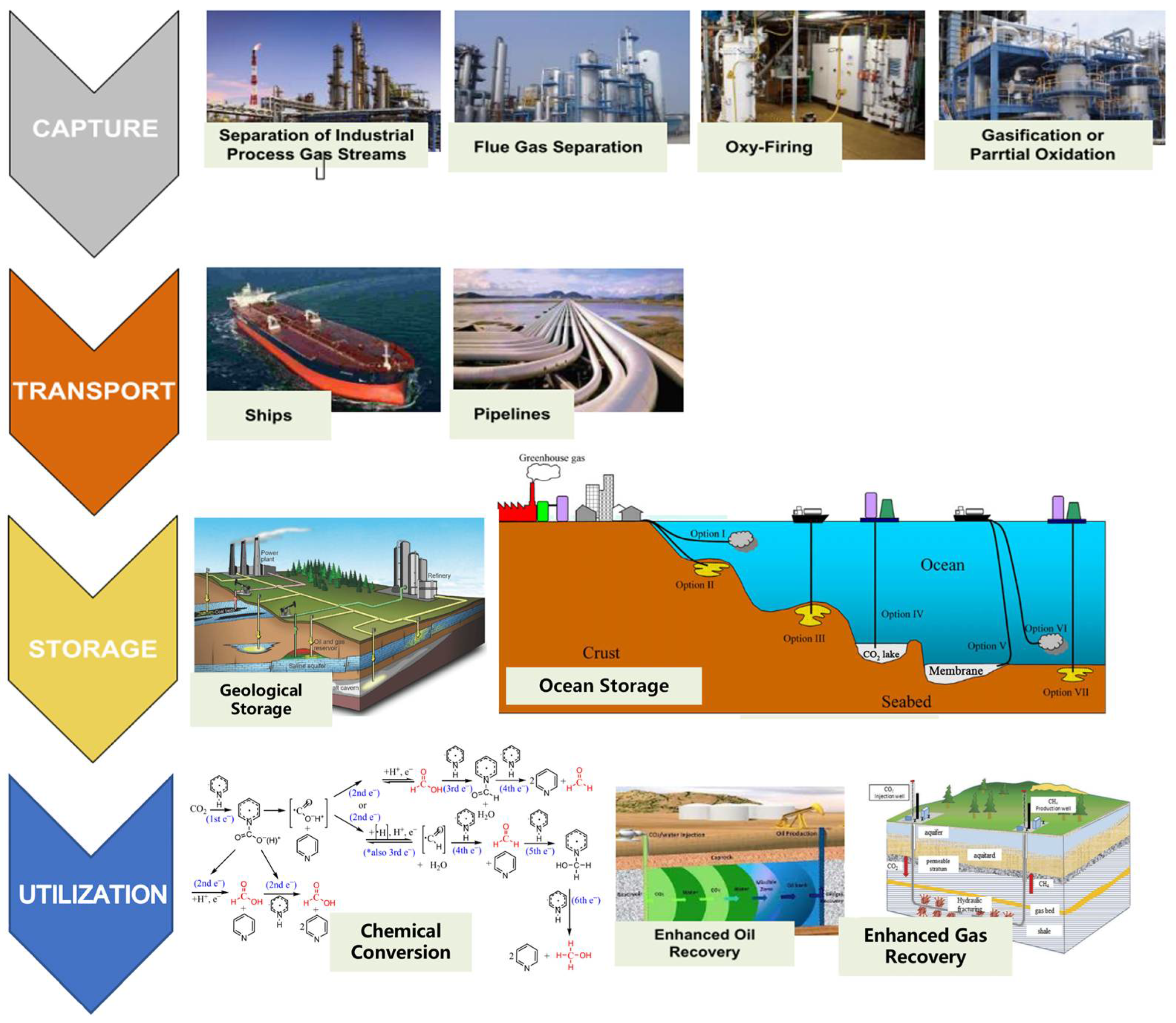
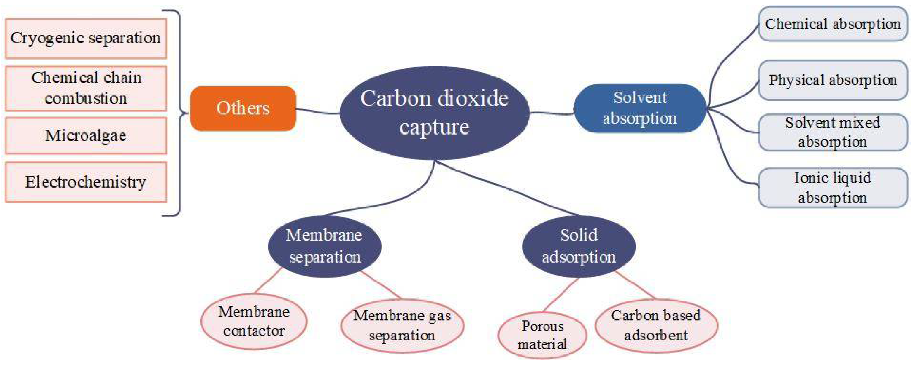
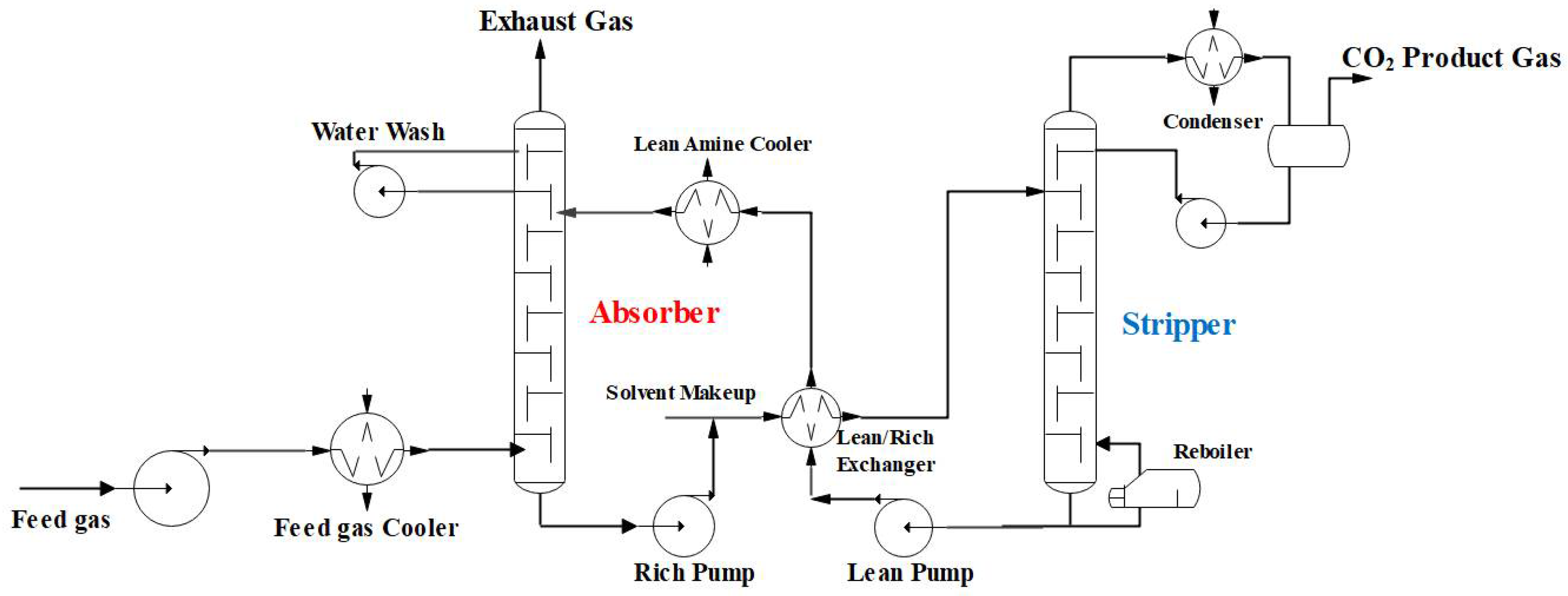
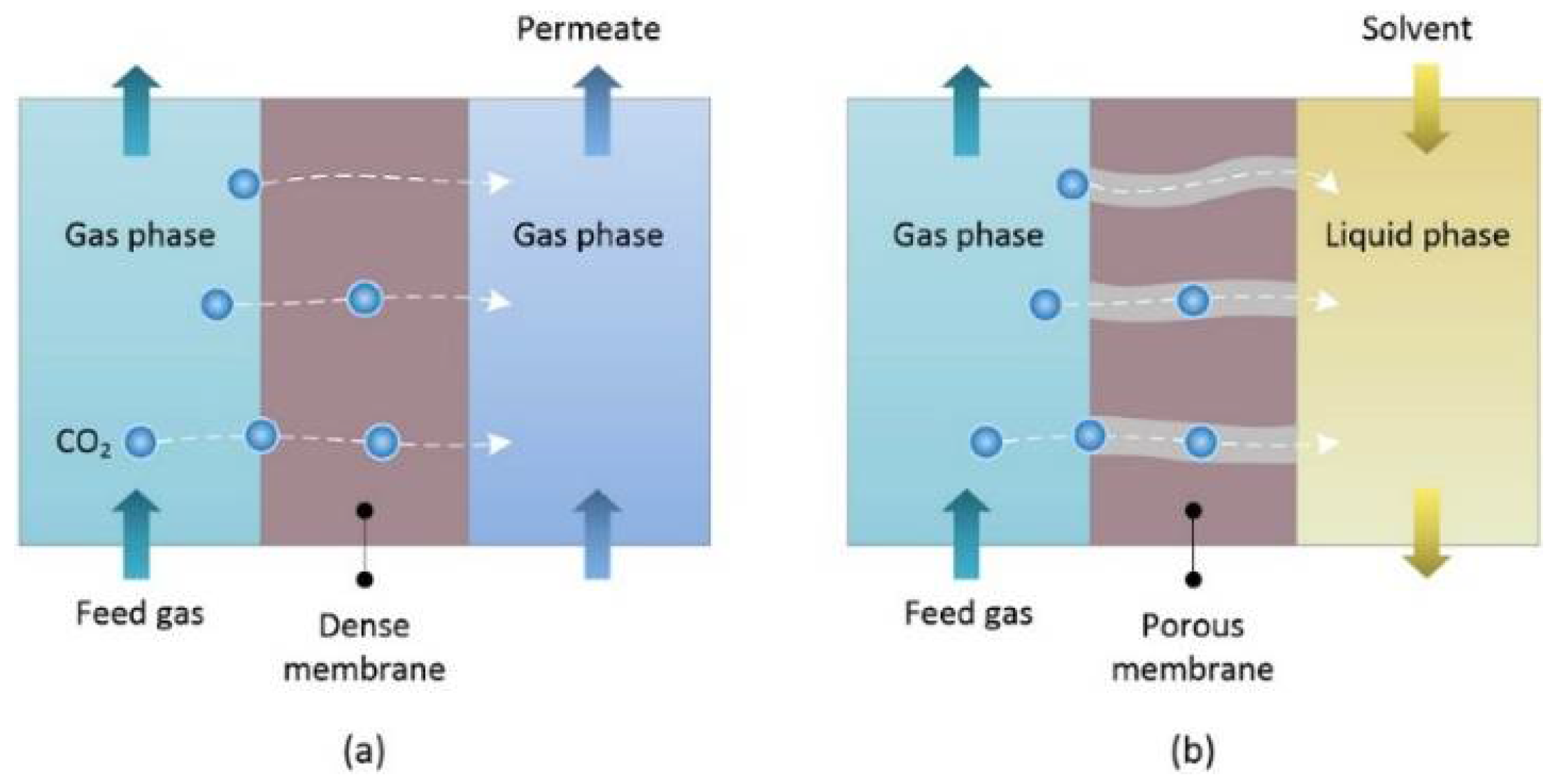
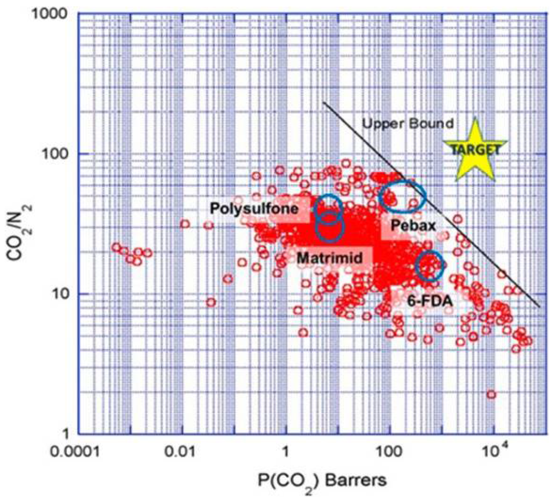
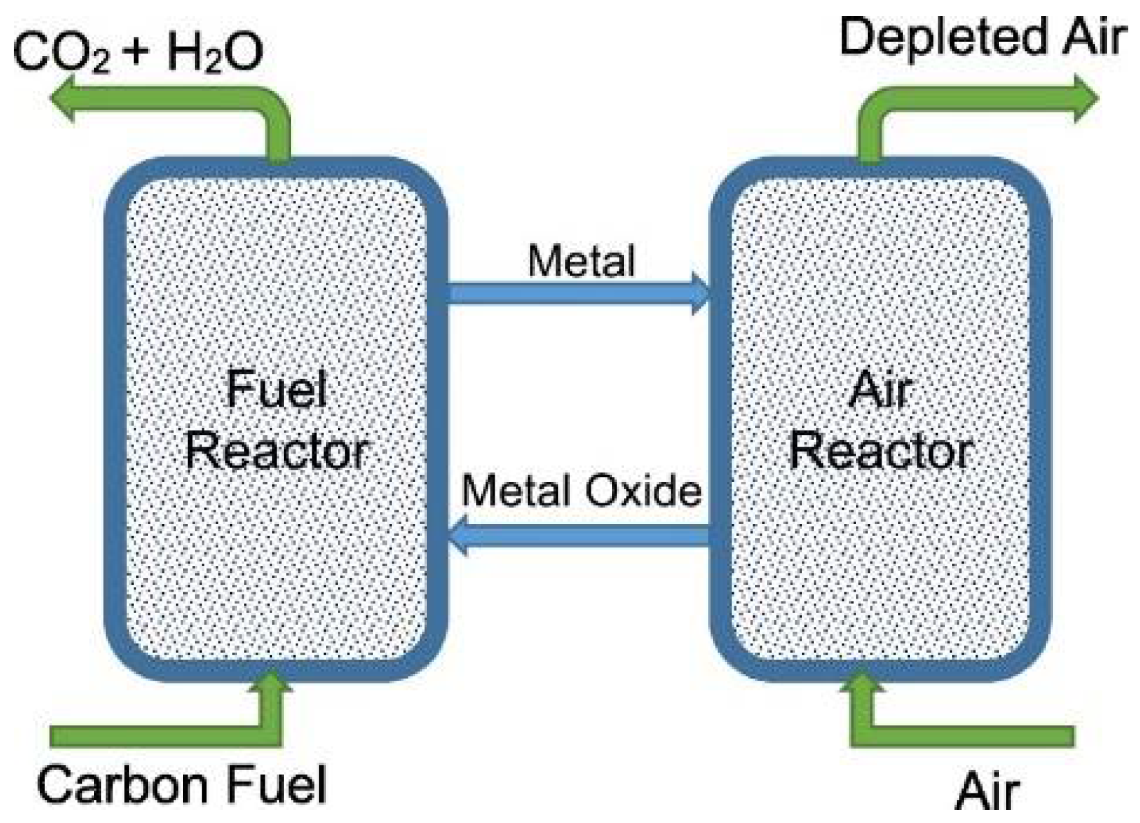
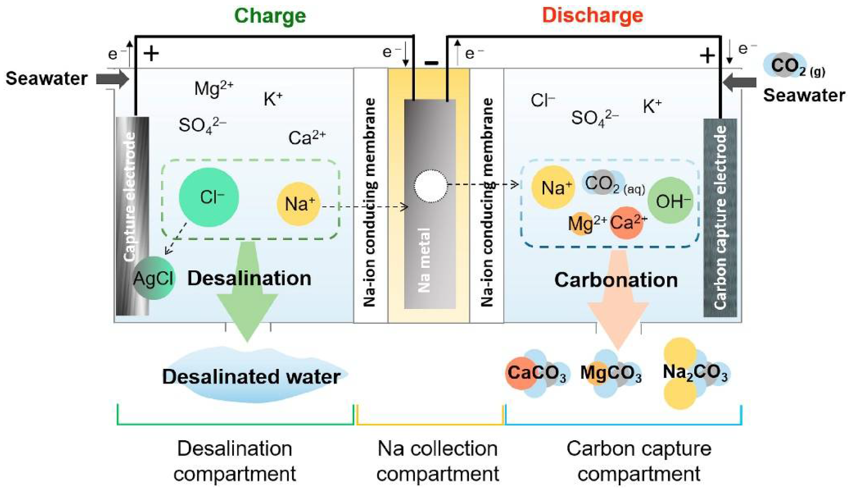
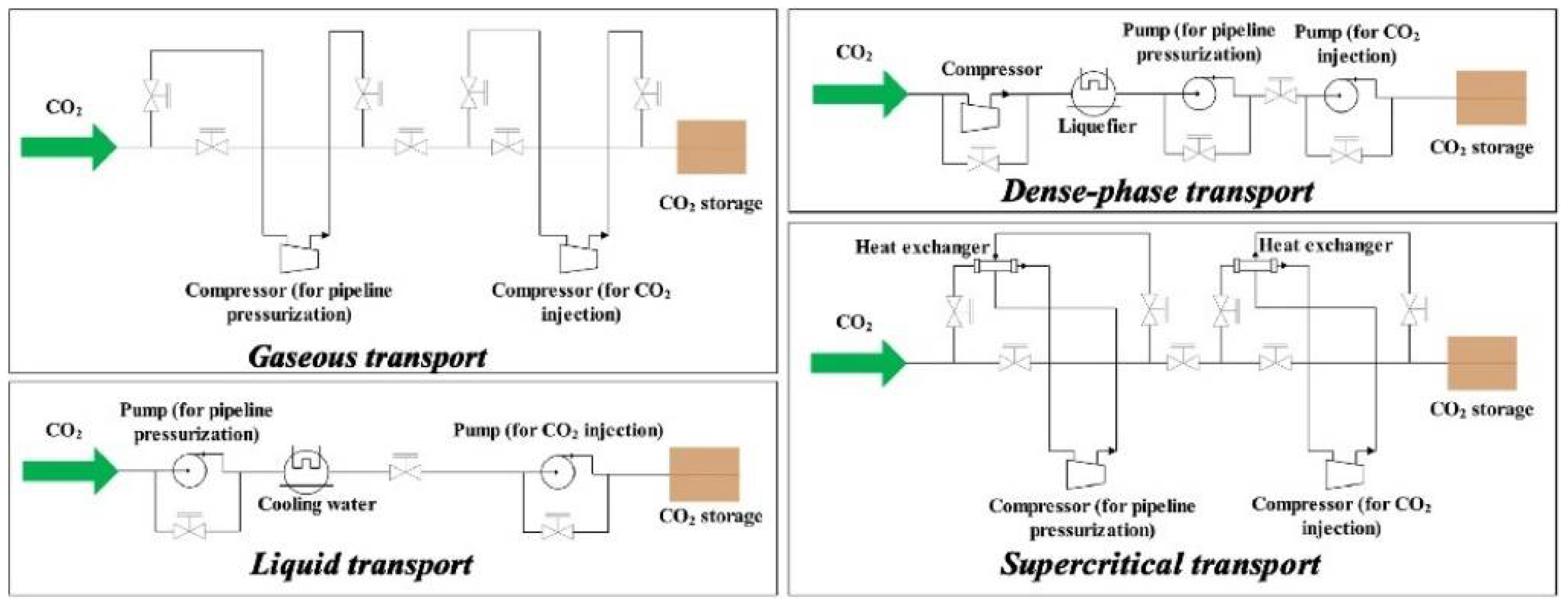
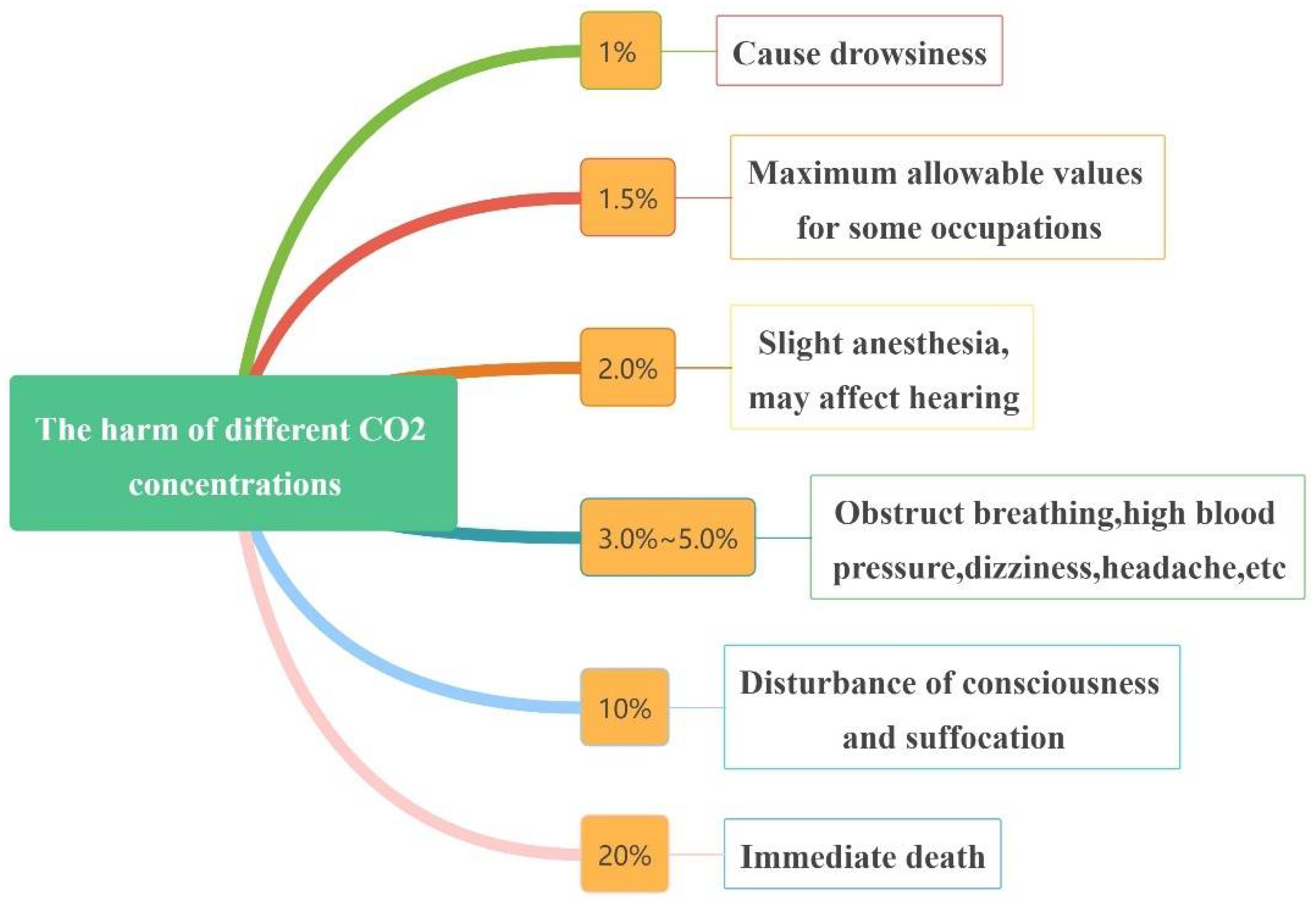
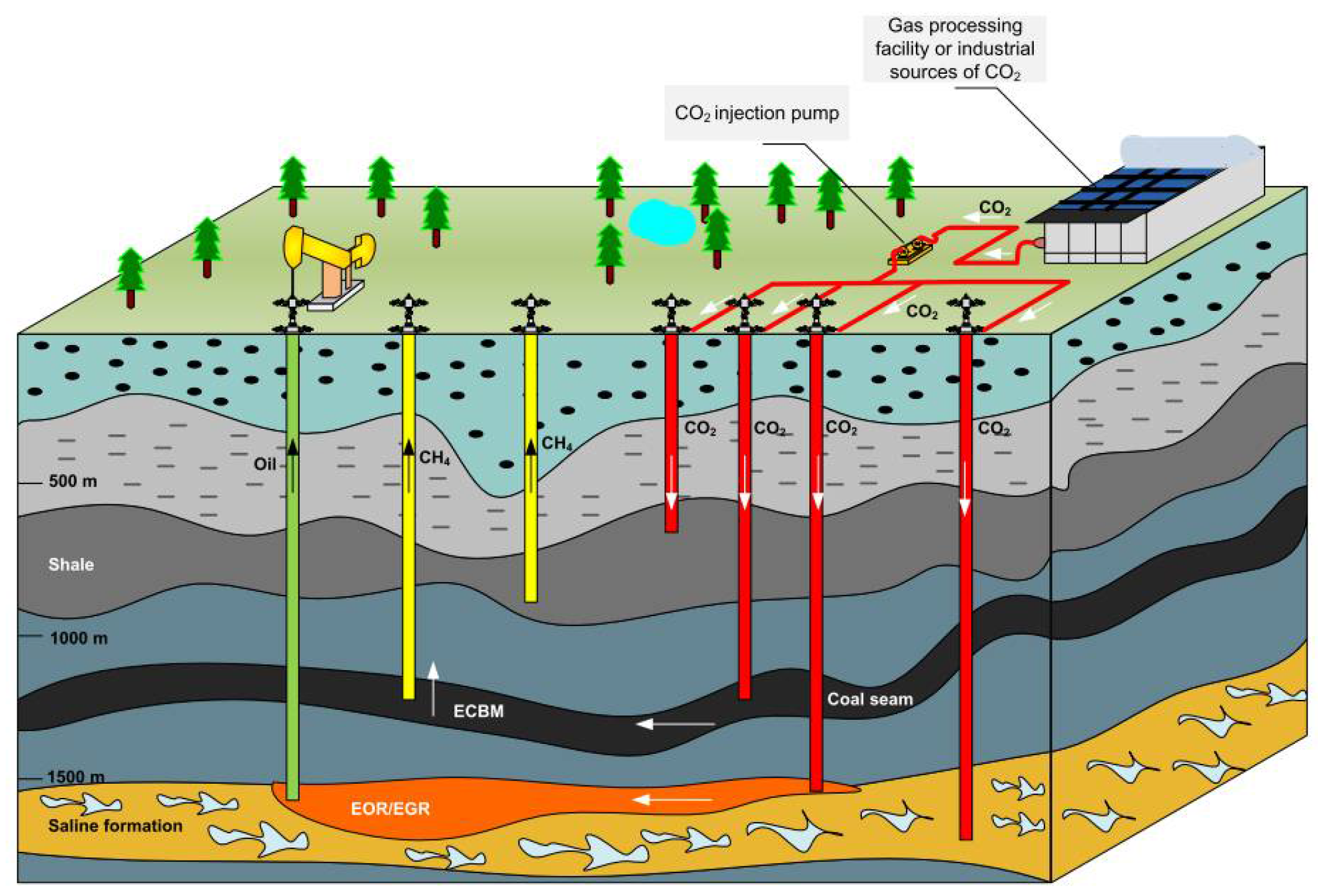
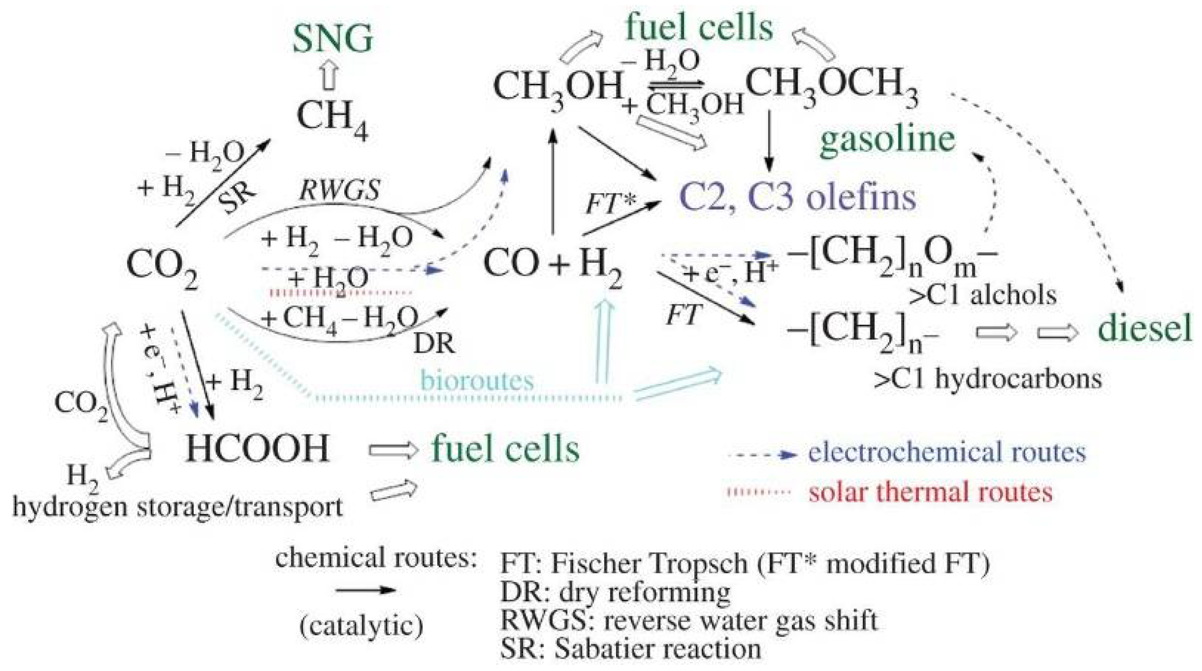
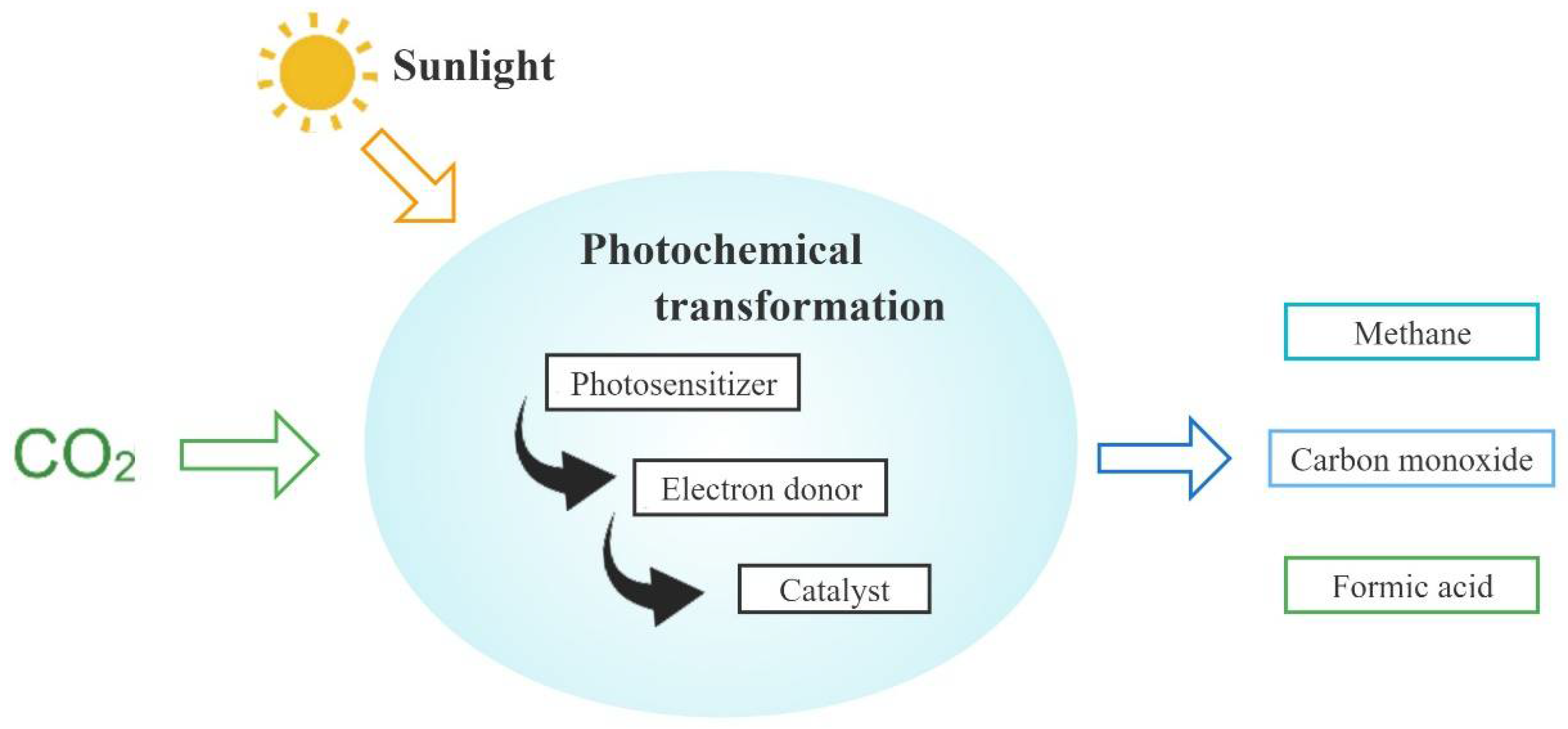
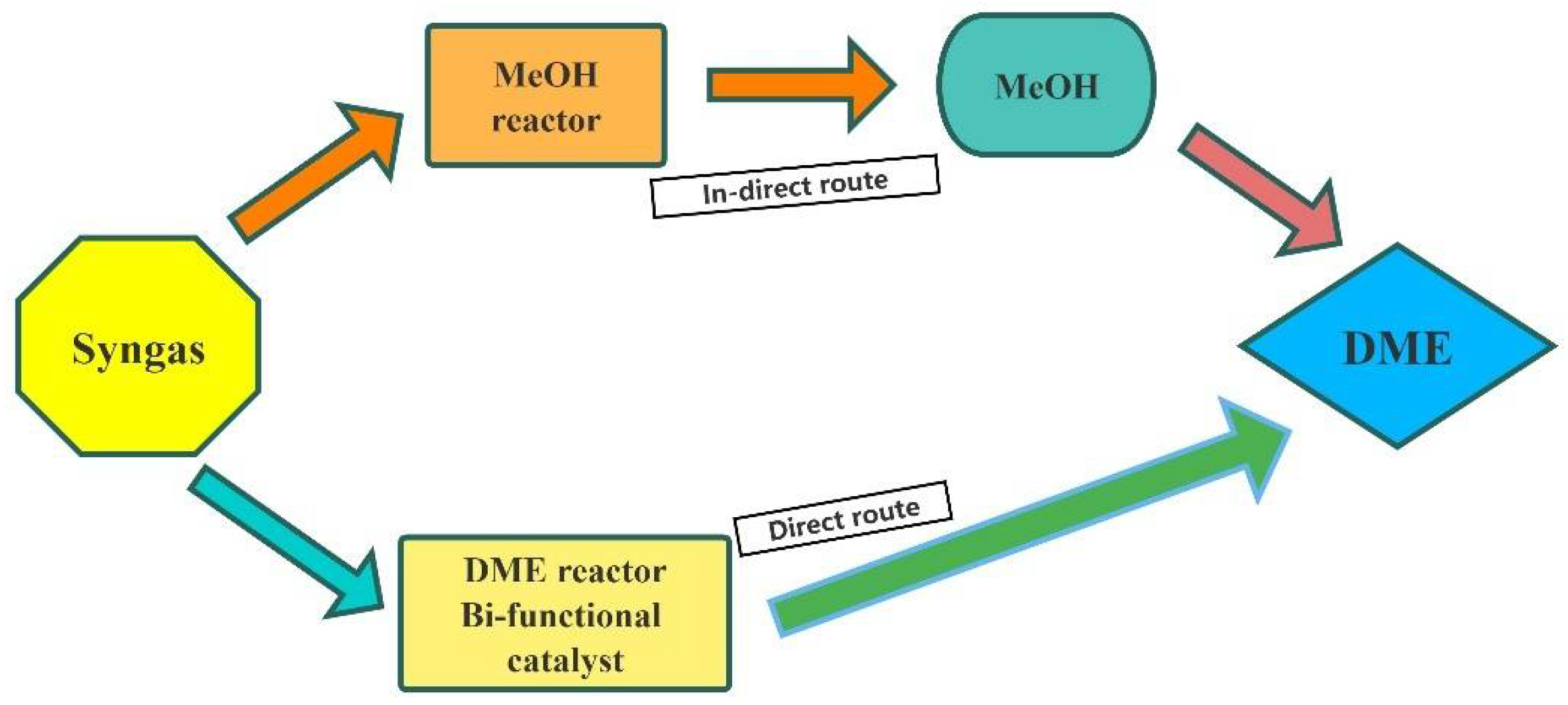
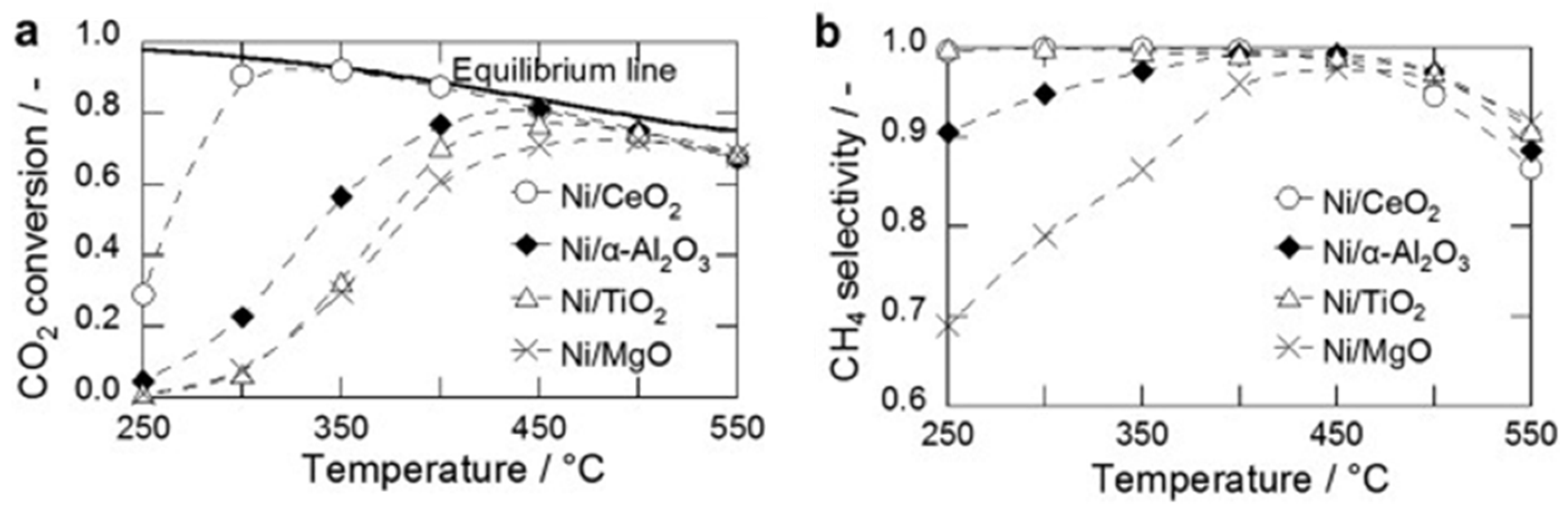
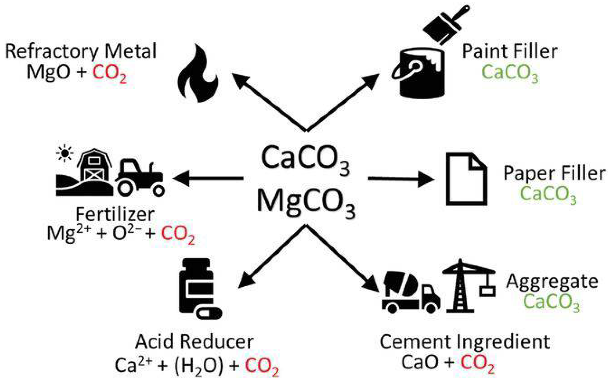
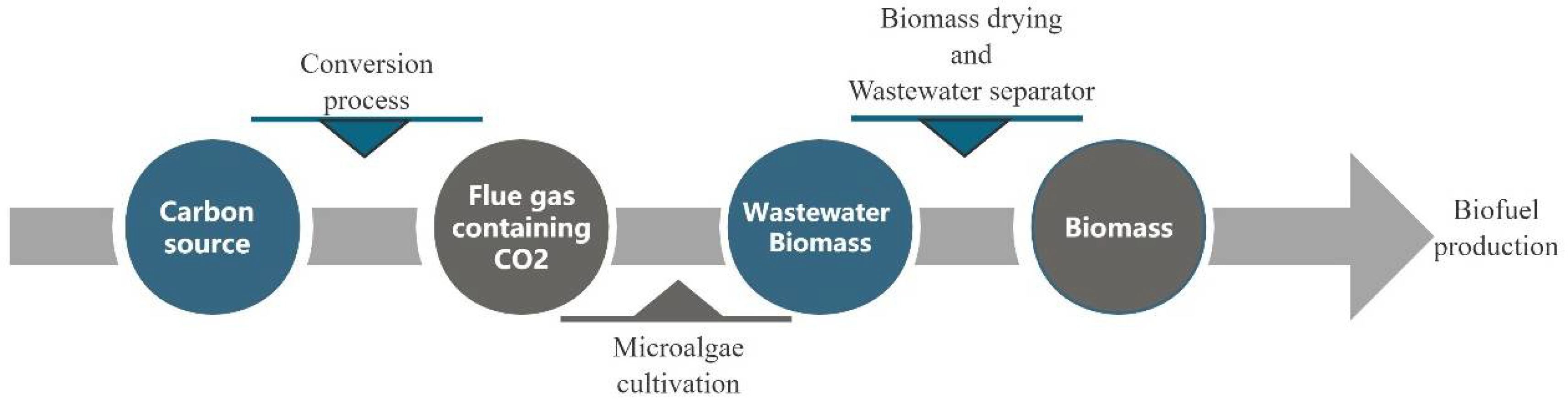
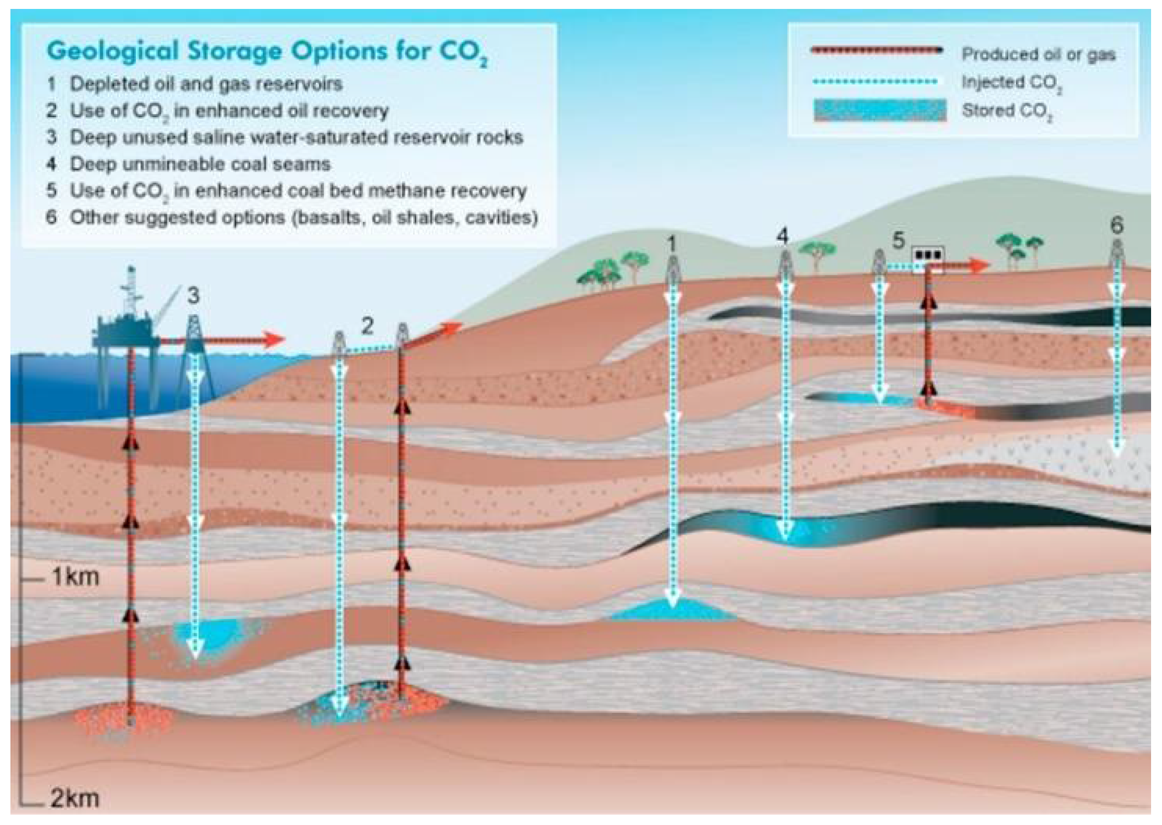
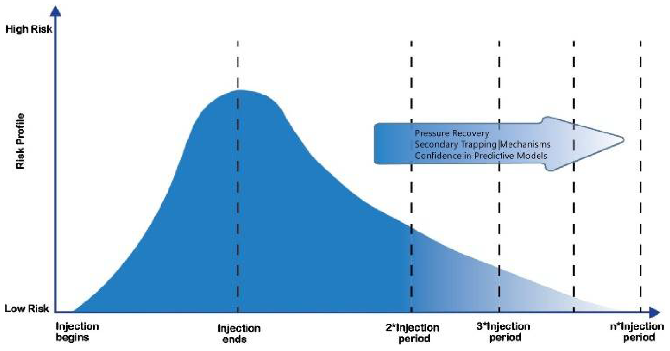
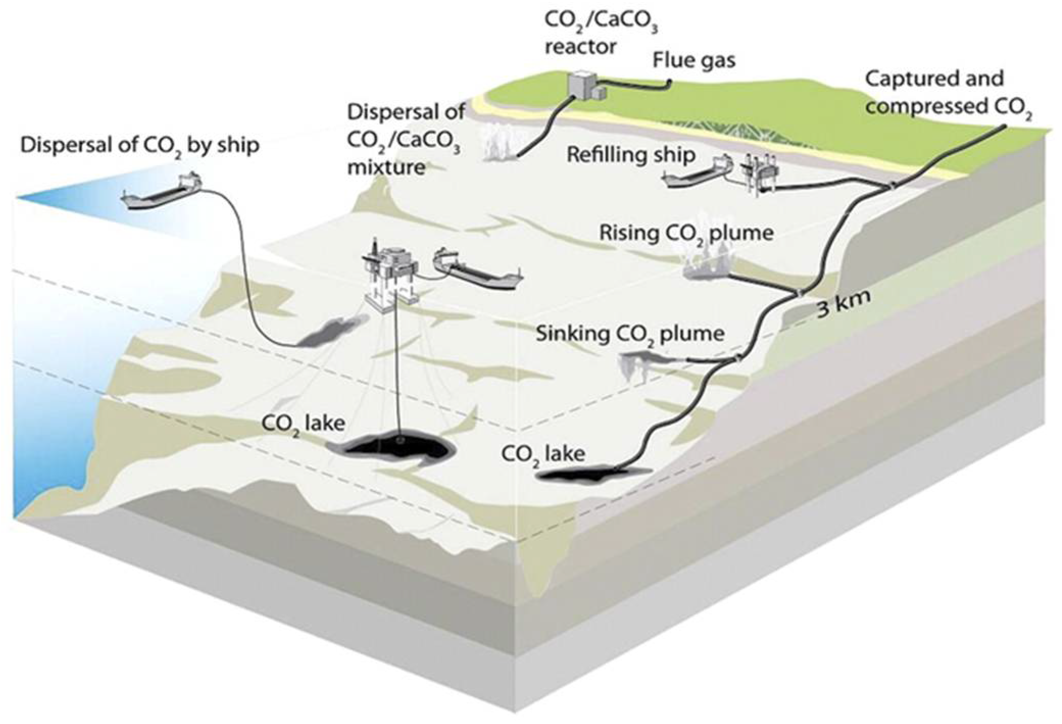
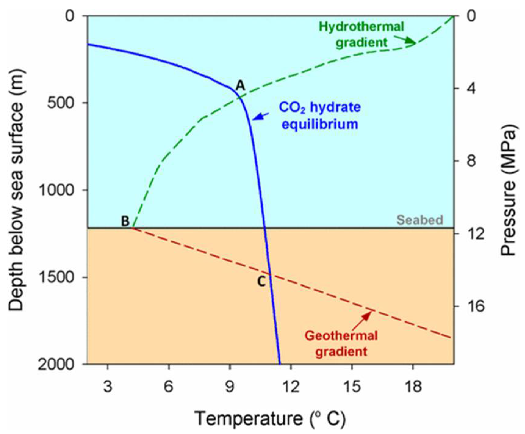
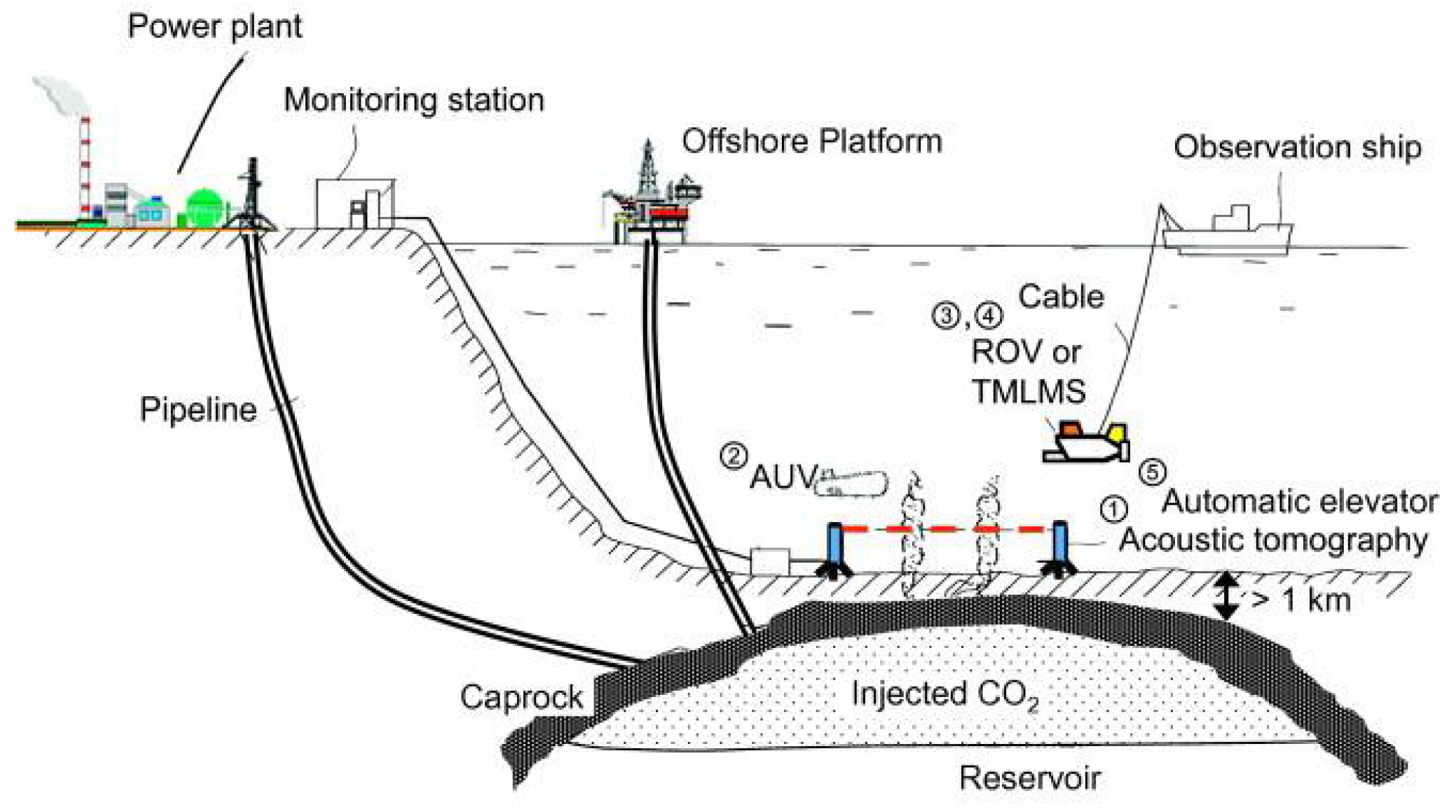
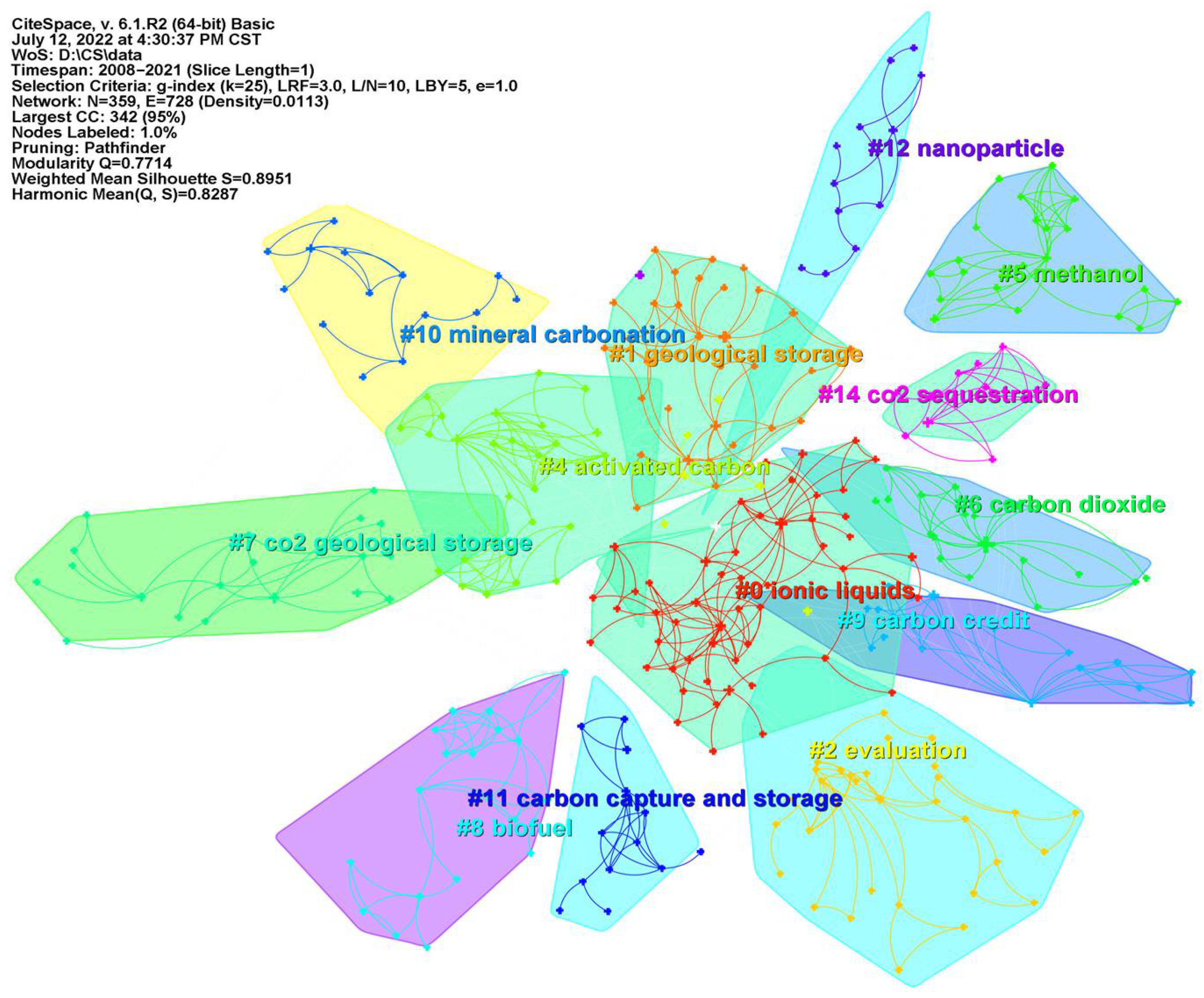
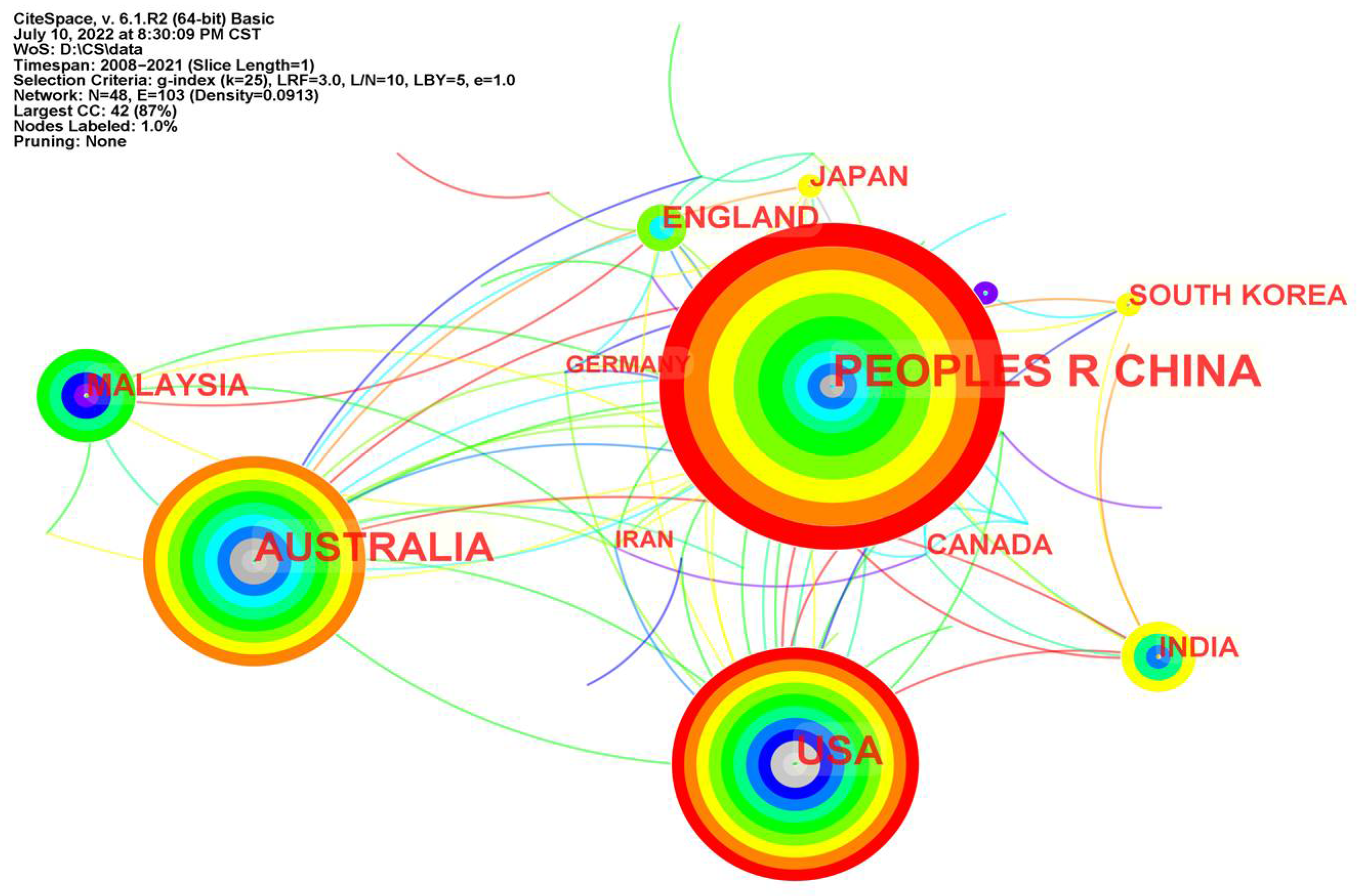
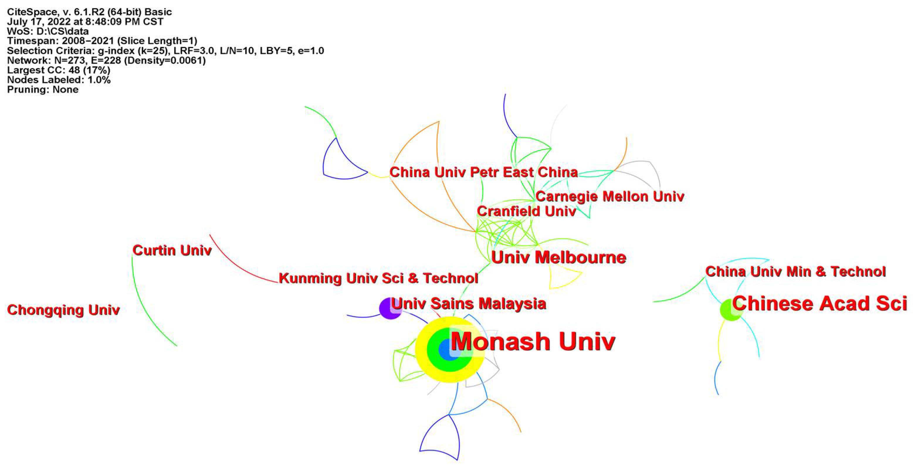
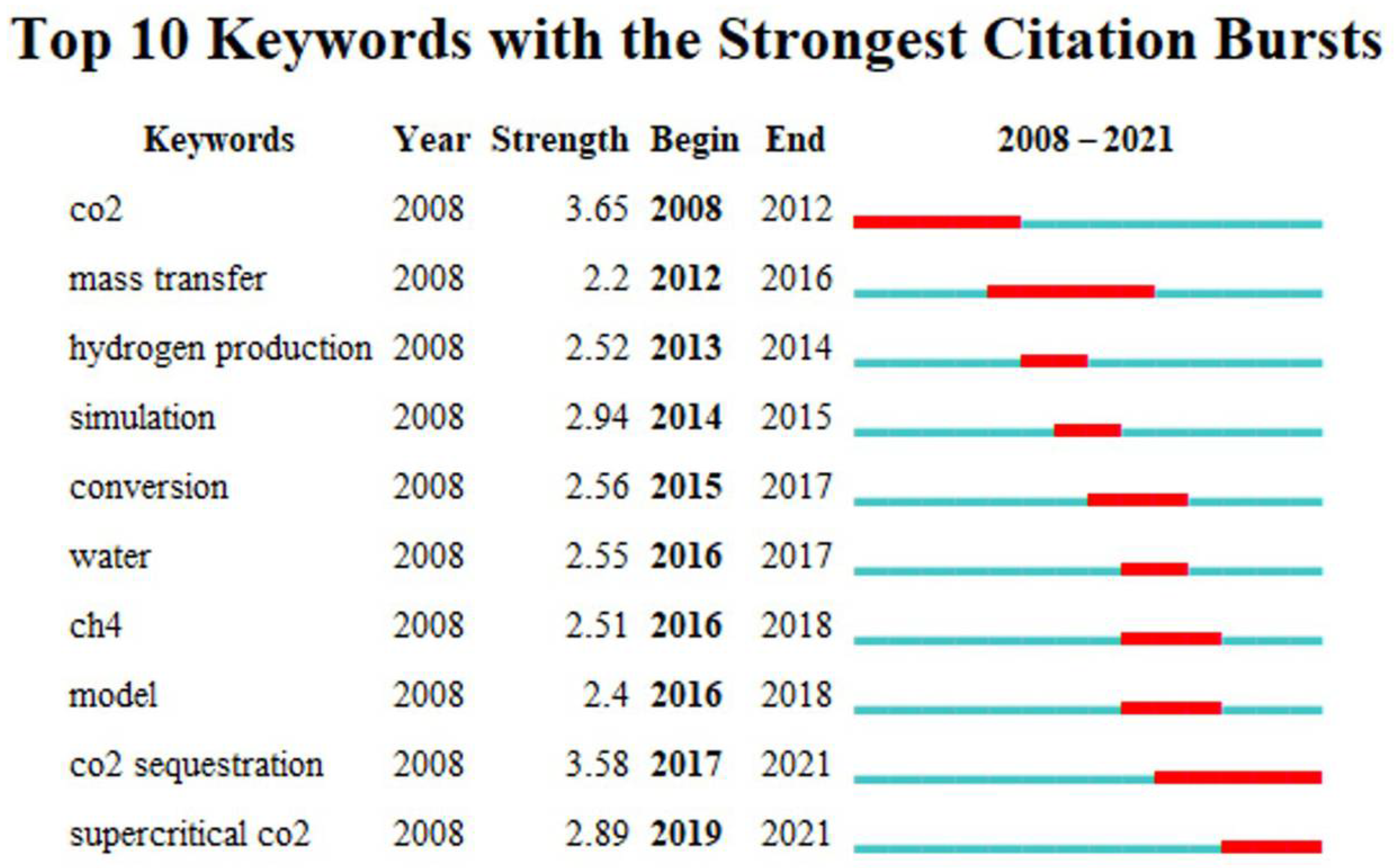
Table 1.
Summary of CCUS-related literature.
| Authors | Content | Year | References |
|---|---|---|---|
| Yao et al. | This paper mainly introduces the latest progress of China’s CCUS after 2019 and finds that China’s CCUS technology has made significant progress in recent years. | 2023 | [6] |
| Hong et al. | This paper summarizes the CCUS system from the technical and economic perspectives, introduces the global CCUS projects, and introduces the progress of various technologies in detail, focusing on the economic comparison of various technologies. | 2022 | [7] |
| Liu et al. | The CCUS path in China was studied, mainly introducing the current situation of CCUS, emission reduction demand and potential cost. | 2022 | [8] |
| Shiyi et al. | Combed the technological development process and industrialization progress of CCUS-EOR, and analyzed the problems and challenges of CCUS-EOR in China. | 2022 | |
| Chen et al. | The risks of CCUS technology in finance, technology, environment, health and safety are introduced. | 2022 | [9] |
| Shen et al. | The low-temperature separation technology is introduced to capture CO2, and the existing problems are summarized. | 2022 | [10] |
| Zhan et al. | Various utilization modes of CO2 are introduced, the progress of CO2 utilization projects is discussed, and the key challenges and problems are studied. | 2020 | [11] |
Table 2.
Comparison of physical absorption methods.
| Method | Propylene Carbonate Method | Polyethylene Glycol Dimethyl Ether Method | Low-Temperature Methanol Washing Method |
|---|---|---|---|
| Applicable conditions | 3~7 Mpa >25 °C | 1.5~14 Mpa 1~25 °C | 3~8.1 Mpa −10~−70 °C |
| Characteristic | the solvent is cheap and non-toxic, suitable for absorbing CO2 from natural gas and crude hydrogen | the process flow is simple, the operation flexibility is large, the one-time purification degree is high, and the total energy consumption is low | methanol is cheap and easy to obtain, with good selectivity, thermal stability and chemical selectivity, and low operating cost |
Table 3.
Carbon Dioxide transportation alternatives [132].
Table 3.
Carbon Dioxide transportation alternatives [132].
| Transporation Method | Conditions | Phase | Capacity | REMARKS |
|---|---|---|---|---|
| Pipelines | 4.8–20 Mpa 283–307 K | gas, liquid, supercritical, dense phase | ~150 Mt CO2/year 8000 km of pipeline transport in operation |
|
| Ships | 0.65–4.5 Mpa 221–283 K | liquid | >70 Mt CO2/year |
|
Table 4.
Selected examples of chemicals currently synthesized from CO2 on a pilot plant scale. a Reproduced with permission from [134], American Chemical Society, 2019.
Table 4.
Selected examples of chemicals currently synthesized from CO2 on a pilot plant scale. a Reproduced with permission from [134], American Chemical Society, 2019.
| Chemical | Company (Location) | Scale Per Year b |
|---|---|---|
| Carbon monoxide (via SOEC) c | Haldor-Topsoe (Lyngby, Denmark)/ Gas Innovations (La Porte, TX, USA) | 12 Nm3/h |
| Methanol | Carbon Recycling International (Reykjavík, Iceland) Mitsui Chemical Company (Tokyo, Japan) | 4000 tons 100 tons |
| Methane | Audi (Ingolstadt, Germany) | 1000 tons |
| Fuels (via CO2-based Fischer-Tropsch) | Sunfire (Dresden, Germany) INERATEC (Espoo, Finland) | 3 tons 200 L |
| Oxalic acid | Liquid Light/Avantium (Amsterdam, The Netherlands) | 2.4 tons |
a A pilot plant is defined as a pre-commercial system, which produces a chemical or fuel on a smaller scale than a full plant and is used for learning purposes. b Amount of product that is produced per year. c SOEC = solid oxide electrolyzer cell.
Disclaimer/Publisher’s Note: The statements, opinions and data contained in all publications are solely those of the individual author(s) and contributor(s) and not of MDPI and/or the editor(s). MDPI and/or the editor(s) disclaim responsibility for any injury to people or property resulting from any ideas, methods, instructions or products referred to in the content. |
© 2023 by the authors. Licensee MDPI, Basel, Switzerland. This article is an open access article distributed under the terms and conditions of the Creative Commons Attribution (CC BY) license (https://creativecommons.org/licenses/by/4.0/).
Share and Cite
MDPI and ACS Style
Liu, E.; Lu, X.; Wang, D. A Systematic Review of Carbon Capture, Utilization and Storage: Status, Progress and Challenges. Energies 2023, 16, 2865. https://doi.org/10.3390/en16062865
AMA Style
Liu E, Lu X, Wang D. A Systematic Review of Carbon Capture, Utilization and Storage: Status, Progress and Challenges. Energies. 2023; 16(6):2865. https://doi.org/10.3390/en16062865
Chicago/Turabian StyleLiu, Enbin, Xudong Lu, and Daocheng Wang. 2023. "A Systematic Review of Carbon Capture, Utilization and Storage: Status, Progress and Challenges" Energies 16, no. 6: 2865. https://doi.org/10.3390/en16062865
Note that from the first issue of 2016, this journal uses article numbers instead of page numbers. See further details here.