Table of Contents
Advertisement
Advertisement
Table of Contents

Related Manuals for Malvern Hydro 2000 G


Summary of Contents for Malvern Hydro 2000 G
- Page 1 Hydro 2000 user manual...
- Page 3 Hydro 2000G/S User Manual MAN0385 Issue 1.0 March 2007...
- Page 4 © Malvern Instruments Ltd. 2007 Malvern Instruments makes every effort to ensure that this document is correct. However, due to Malvern Instruments’ policy of continual product development we are unable to guarantee the accuracy of this, or any other document after the date of publication. We therefore disclaim all liability for any changes, errors or omissions after the date of publication.
-
Page 5: Table Of Contents
T able of Contents Part 1 - Operator’s Guide Introduction to this manual ..........1-1 Introduction . - Page 6 Table of Contents Hydro 2000G/S Part 2 - Appendices Specification ..........A-1 Hydro 2000G .
-
Page 7: Part 1 - Operator's Guide
Part 1 - Operator’s Guide... -
Page 9: Introduction To This Manual Introduction
Users must read the Health and Safety information in the Essentials Manual before operating the system. We recommend that users who have never operated a Malvern particle analyser before read this manual fully before starting the first measurement. Hydro 2000G/S... -
Page 10: Access To The Instrument
Below is a list of these people and their responsibilities: Malvern personnel Malvern personnel (service engineers, representatives, etc.) have full access to the dispersion unit and are authorised to perform all service procedures that may require the removal of the covers. -
Page 11: Assumed Information
“the system”. Menu commands Menu commands from the Malvern software are referred to in the form main menu-menu item. As an example, the command Configure-New SOP refers to selecting the New SOP item in the Configure menu. The same rules apply for... - Page 12 Chapter 1 Introduction to this manual Page 1-4 MAN 0385...
-
Page 13: Hardware Features
Hardware features Introduction This chapter describes the physical features of the dispersion unit. It covers: What the dispersion unit does. How the dispersion unit works. How the dispersion unit is controlled. The physical features of the Hydro 2000G in detail. The physical features of the Hydro 2000S in detail. -
Page 14: How The Dispersion Unit Works
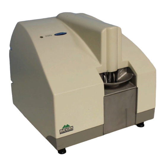
Chapter 2 Hardware features How the dispersion unit works This is the Hydro 2000G: 2, 3 ill 4911 The dispersion unit comprises a tank that holds one litre of sample/dispersant liquid. A stirrer , controlled from the software, agitates the sample and stops it ... -
Page 15: How The Dispersion Unit Is Controlled
More details on the tank area are given below. An ultrasonic probe also helps to disperse the sample. All functions of the tank area are controlled by the Malvern software. Status indicator... - Page 16 Chapter 2 Hardware features amber if the dispersion unit is functioning correctly but its cell has not been loaded into the optical bench. (i.e. the dispersion unit is at “standby”) red if the dispersion unit detects an error. If an error message does not appear on the screen, selecting Configure-Accessory displays the accessory control dialogue which should show the error.
- Page 17 Hardware features Chapter 2 These are the following: Tank The tank can hold up to one litre of sample and dispersant for circulation through the cell of the optical bench. Warning! Due to the possible risk of sonication of the blood and its unknown effects, never place fingers in the tank when the ultrasonic probe is in operation.
- Page 18 Chapter 2 Hardware features threshold settings may need adjusting. The Essentials Manual has more details on cleaning the level sensor. The level sensor must be set to detect different types of dispersant by setting the level sensor threshold. This is done by selecting Configure-Accessories. The Level Sensor Threshold section is shown below: Use the up and down arrows to set the threshold for the dispersant used then click the Apply button.
- Page 19 Hardware features Chapter 2 Rear panel This illustration identifies the main features of the rear panel: ill 4913 These are the following: Drain The drain port is the exit point where sample/dispersant leaves the dispersion unit. A warning triangle warns that the contents of the tank are drained from this pipe. The risk depends on the hazardous nature of the dispersants/samples being meas- ured.
- Page 20 Chapter 2 Hardware features Tank fill rate This adjuster alters an internal pressure regulator that will control the rate at which the tank is filled with dispersant. This is always set by the installation engineer but if it’s found that the dispersant pressure has changed (one sign is that the tank takes a long time to fill), alter this adjuster so that a fill tank cycle takes about 20 seconds.
- Page 21 Hardware features Chapter 2 Flow cell The flow cells for the Hydro 2000S and Hydro 2000G are identical except for internal identification encoding and the label badge. This diagram shows the cell: ill 4915 The flow cell passes the sample/dispersant through the analyser beam of the optical bench so that it can be measured.
- Page 22 Chapter 2 Hardware features Cell windows The cell windows allow the analyser beam of the optical bench to pass through the cell and hence the particle field. The cell windows can be removed to allow clean- ing (the cell window tool used to remove the window is located within the cell holder).
-
Page 23: Features Of The Hydro 2000S
More details on the tank area are given below. An ultrasonic probe also helps to disperse the sample. All functions of the tank area are controlled by the Malvern software. Status indicator... - Page 24 Chapter 2 Hardware features Cell holder The Mastersizer system is designed so that more than one dispersion unit can be connected at once. The cell holder provides a convenient storage location for the flow cell if another dispersion unit is in use. The cell holder reduces the build up of dust on the cell windows when not in use.
- Page 25 Hardware features Chapter 2 Tank The tank can hold up to 150ml of sample and dispersant for circulation through the cell of the optical bench. Sample and dispersant can be directly poured into the tank. If doing so, do not overflow the tank by filling it too quickly.
- Page 26 Chapter 2 Hardware features Use the up and down arrows to set the threshold for the dispersant then click the Apply button. The values of some commonly used dispersants are listed below. Water (default) - 64% White spirit - 36% Propan-2-ol - 64% 2-2-4 Trimethyl pentane - 36% The level sensor threshold must always be set when a different dispersant is used.
- Page 27 Hardware features Chapter 2 from this pipe. The risk depends on the hazardous nature of the dispersants and samples being measured. The drain pipe should not exceed 2m in length and should have no loops or kinks. Dispersant input port The dispersant input is the inlet port which is connected to a clean source of dis- persant.
- Page 28 Chapter 2 Hardware features Hydro 2000S flow cell The flow cells for the Hydro 2000S and Hydro 2000G are identical except for internal identification encoding and the label badge. Refer to the Flow Cell section for the Hydro 2000G above to identify the features of the cell.
-
Page 29: Software Features
Software features Introduction This chapter describes the features of the software which are specific to the disper- sion unit. It covers: Making a measurement – the basics of making a measurement using the dis- persion unit. Manually controlling the dispersion unit. Writing a Standard Operating Procedure (SOP) for the dispersion unit. -
Page 30: Manually Controlling The Dispersion Unit
Chapter 3 Software features Manually controlling the dispersion unit To control the dispersion unit manually, either select Configure-Accessory or, when making a manual measurement, click the Accessory button in the Meas- urement Display window. The accessory control dialogue shown below appears: ill 7757 The contents of this dialogue change depending on the dispersion unit connected. - Page 31 Software features Chapter 3 Note For the Hydro 2000S the Pump and Stirrer slide bars are combined into a single slider. Pump control The speed of the pump is altered by moving the slider. Use the up and down arrows under the slider for fine adjustment of the pump speed.
- Page 32 Caution! Never leave sample in the tank for long periods - always flush the tank and leave it filled with clean dispersant. Contact the Malvern representative if the Drain Valve Error indicator illuminates. Stirrer Error – illuminates if the stirrer fails to reach the requested speed.
-
Page 33: Writing An Sop For The Dispersion Unit
Software features Chapter 3 Writing an SOP for the dispersion unit An SOP can be configured to control all settings for the dispersion unit automati- cally. When an SOP is run, the software will (depending on how the SOP has been set up) automatically fill the tank, flush the tank to clean it, run a de-gas routine to remove bubbles from the dispersant and then set the pump, stirrer and ultrasound to predefined settings. - Page 34 Chapter 3 Software features All systems the SOP is distributed to must have the dispersion unit connected. Sampler Settings dialogue The Sampler Settings dialogue controls the pump, stirrer and ultrasonic settings for the dispersion unit. This dialogue changes depending on the dispersion unit selected in the Sampler Selection dialogue.
- Page 35 Software features Chapter 3 Continuous (from start) – ultrasound is active throughout the measure- ment. Ultrasound will start after the electrical background is complete. The stabilising period will add a delay between the electrical background and the optical alignment. During this delay ultrasound will be operating, allowing bubbles to be driven from the dispersant.
-
Page 36: Advanced Software Features: Vari-Flow
Chapter 3 Software features Advanced software features: Vari-flow Some materials, such as metal flakes, may form structures when they are circulated through the flow cell at normal pump speeds. These structures cause a secondary diffraction pattern that is incorrectly interpreted as a small peak at 1000 microns. Vari-flow (accessed by selecting the Advanced button in the Sampler Settings dialogue) allows these materials to be dispersed in the tank in the normal way. - Page 37 Software features Chapter 3 The pump speed falls to a predetermined reduced level (Reduced pump speed in the dialogue - this can be zero) and an additional Measurement delay allows the background level to fall before the alignment is performed and the background measured.
- Page 38 Chapter 3 Software features Page 3-10 MAN 0385...
-
Page 39: Part 2 - Appendices
Part 2 - Appendices... -
Page 41: Specification
Specification Hydro 2000G Dispersion type Capacity 1 litre Typical applications Minerals, fillers, chemicals, foodstuffs, emulsions Dispersion mechanisms Continuously variable and independent pump, stirrer and ultrasonics. Modes of operation Automatic via SOPs. Manual via computer operating dialogues. Weight 18.7kg Dimensions Width: 348mm Height: 333mm Depth: 365mm Power... -
Page 42: Hydro 2000S
Appendix A Specification Hydro 2000S Dispersion type Capacity 50-150ml Typical applications Solvent-based suspensions, Pharmaceuticals. Dispersion mechanisms Continuously variable combined pump/stirrer. Continuously variable ultrasonics Modes of operation Automatic via SOPs. Manual via computer operating dialogues. Weight 16.8kg Dimensions Width: 348mm Height: 333mm Depth: 365mm Power 100-120V / 200/240 V AC, 50/60Hz, 240VA... -
Page 43: Chemical Compatibility
Cell Glass, 316 stainless steel, Viton Splash guard (Hydro 2000G only) Acrylic Note For the Hydro 2000S Viton seals can be upgraded to Perlast to improve ™ the chemical compatibility. Contact the Malvern representative for details. Hydro 2000G/S Page B-1... - Page 44 Appendix B Chemical compatibility Page B-2 MAN 0385...
-
Page 45: Regulatory Statements
Regulatory statements This section presents the CE Declarations of Conformity for the products. Hydro 2000G/S Page C-1... -
Page 46: Ce Declaration Of Conformity (Awa2000
Appendix C Regulatory statements CE Declaration of Conformity (AWA2000) The CE badge on this product signifies conformance to European Commission Directives. ill 8007 Page C-2 MAN 0385... -
Page 47: Ce Declaration Of Conformity (Awa2001
Regulatory statements Appendix C CE Declaration of Conformity (AWA2001) The CE badge on this product signifies conformance to European Commission Directives. ill 8006 Hydro 2000G/S Page C-3... - Page 48 Appendix C Regulatory statements Page C-4 MAN 0385...
-
Page 49: Index
Index Accessory chaining Features overview 2-15 Accessory control dialogue Flow cell Air purge inlet details Air supply (purge) Hydro 2000S 2-16 Fluid handling valves From cell pipe 2-15 FROM CELL port Capacities CE Declaration Cell holder overview Help 2-4, 2-12 Cell in connector Hydro 2000G features 2-10... - Page 50 Index Hydro 2000G/S Pipe grommets 2-10 Power requirements A-1, A-2 Tank Pre-measurement period box cleaning Pump and stirrer settings emptying Pump control filling 2-5, 2-13, 3-3 Pump error Tank area Pump speed details 2-4, 2-12 changing 2-3, 3-2 overview 2-3, 2-11 Pump/stirrer 2-5, 2-13 Tank fill rate...