


What Is the Symbol for a Simple Hole?
The symbol used for a hole is the diameter ‘Ø’ symbol.
How Are Simple Holes Shown on Engineering Drawings?
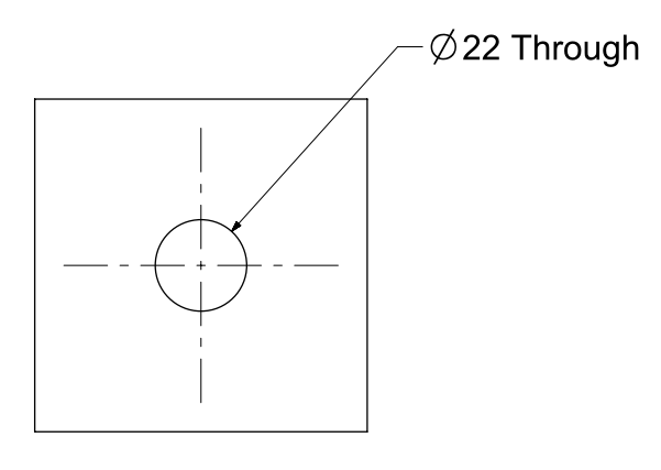
Simple holes are shown on engineering drawings by stating the diameter and the depth of the hole.
For example, a 20 diameter hole that goes straight through the component would be represented as “Ø20 Through”.
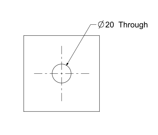
Holes that go all the way through the component are known as through holes.
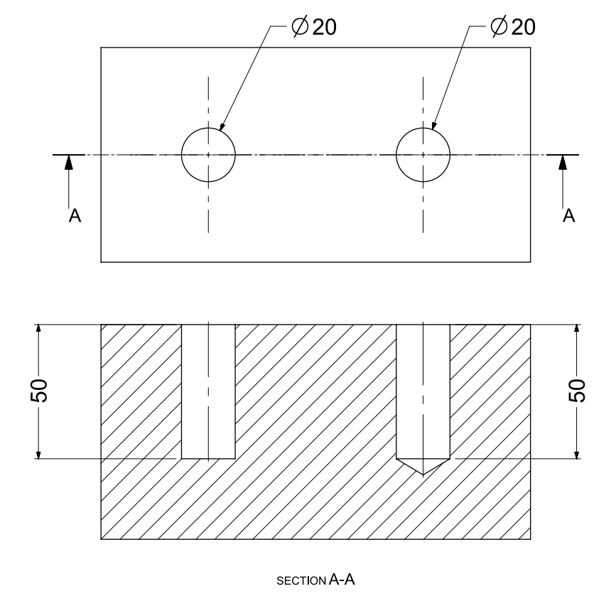
Holes that do not go completely through the material are known as blind holes.
Holes can be shown as a section view in order to show a clearer image of the depth of the holes.
The bottom view is what we would see if we cut the top view in half along the ”A’ section line.
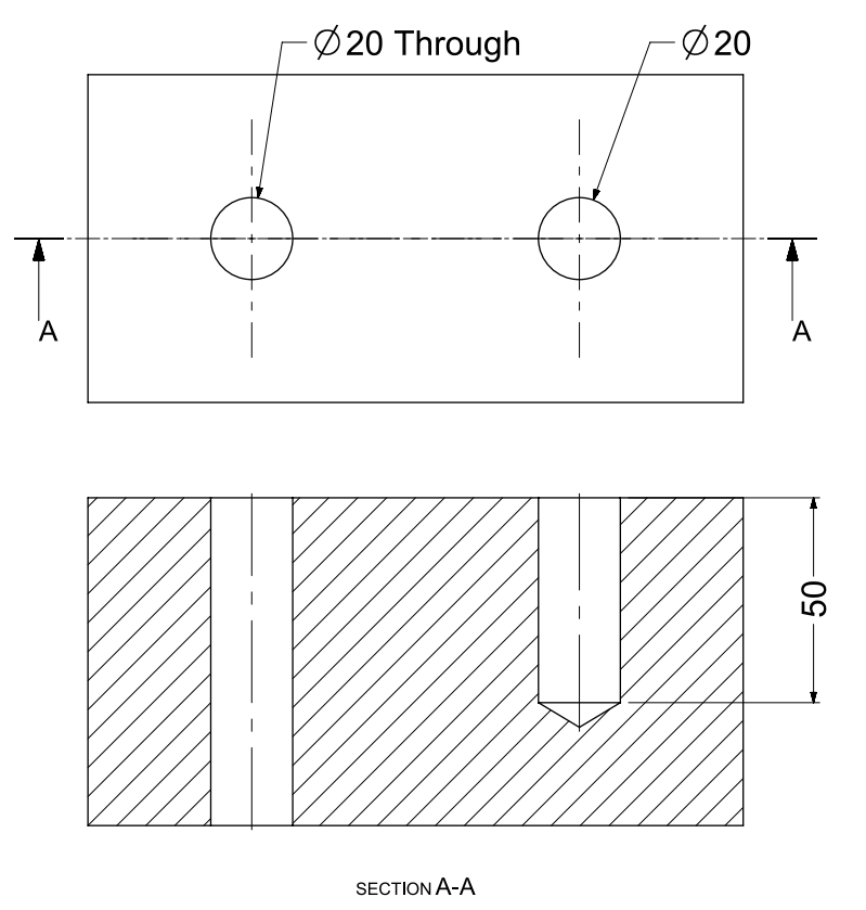
The shape of the bottom of the hole is determined by the tool used to create the hole.
For a drilled hole, the shape of the bottom of the hole will be determined by the drill tip angle.
If the hole is created by a process called ‘boring’ or by a tool with a zero tip angle, the bottom of the hole will be flat.
These two types of blind hole drilling are shown in the drawing below:
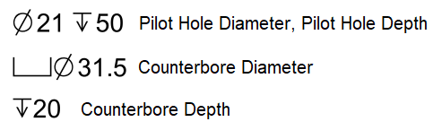
What Is the Counterbore Symbol?
The symbol used for a counterbore is ‘⌴’.
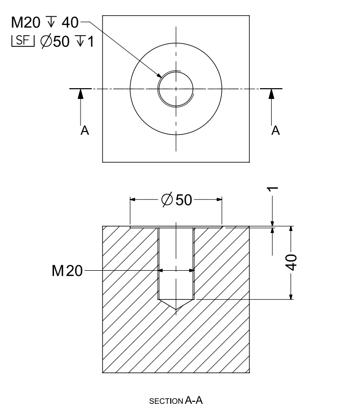
How Are Counterbores Shown on Engineering Drawings?
Counterbored holes are shown on engineering drawings as follows:
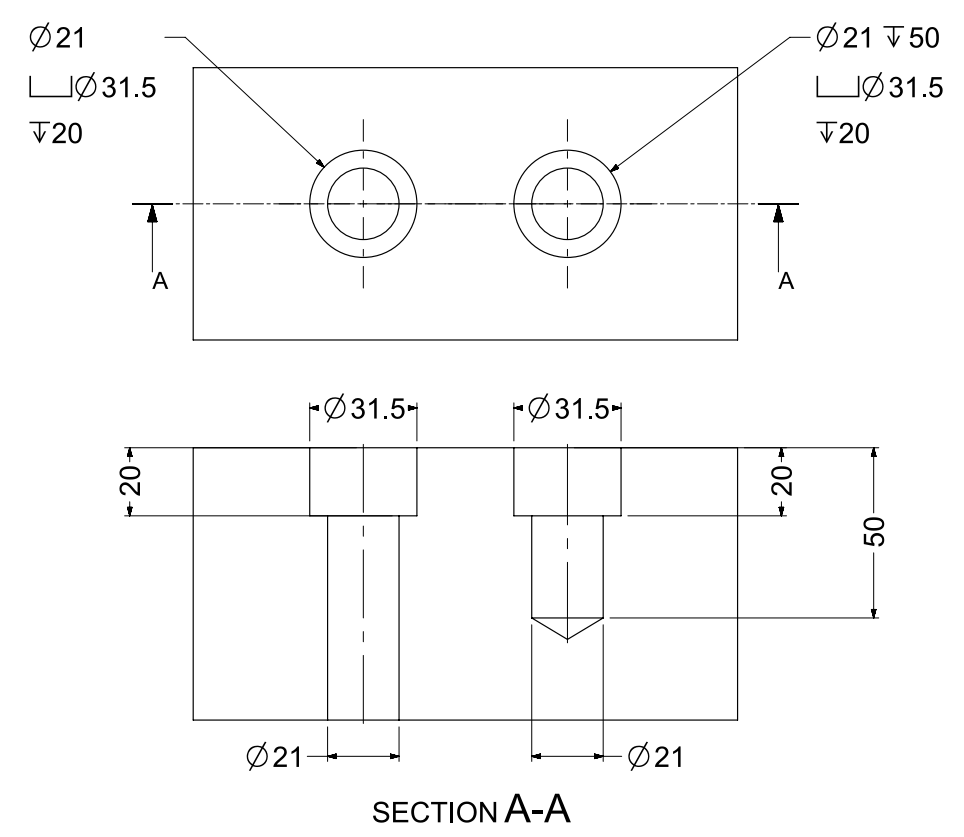
The top view shows how counterbored holes are shown on drawings. The bottom view explains what the counterbore dimensions are showing.
Note for counterbored holes that the pilot hole usually goes completely through the component. That’s why there isn’t a ‘Through’ or a dimension after the pilot hole diameter, because it is assumed it goes all the way through.
A ‘pilot hole’ is a small diameter hole, usually the first hole to be drilled.
The counterbore example above was for an M20 socket-head bolt with normal clearance. You can find out what size counterbore you need by looking at a chart such as this one.
What Are Counterbored Holes Used For?
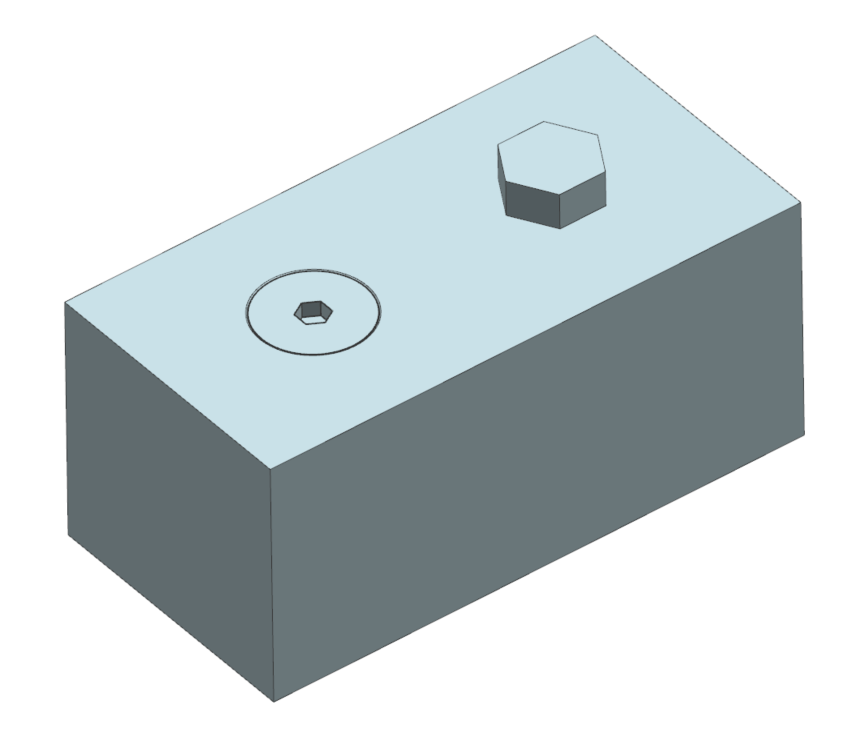
Counterbores are machined for socket-head screws. They are used for applications where the bolt or screw must sit beneath the surface.
For example, in applications where there isn’t space for a hex-head bolt to be used due to clearance issues:
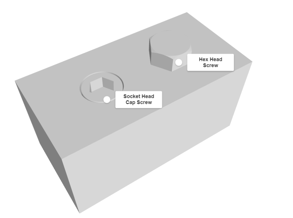
A washer may also be present underneath the socket-head screw.
Spotface
What Is a Spotface?
A spotface is a shallow counterbored hole.
What Is the Spotface Symbol?
The symbol for a spotface is the counterbore symbol with the letters ‘SF’ inside it:

How Are Spotfaces Shown on Drawings?
An example of a spotface is shown below, the dimensioning is very similar to a counterbore.
What Are Spotfaces Used For?
Spotfaces are used for creating a smooth and flat surface.
For example, a component that has been made via casting may not have a smooth and flat surface like a machined component.
Therefore a spotface is machined, ensuring that a part to be connected to a component with a rough surface is located correctly.
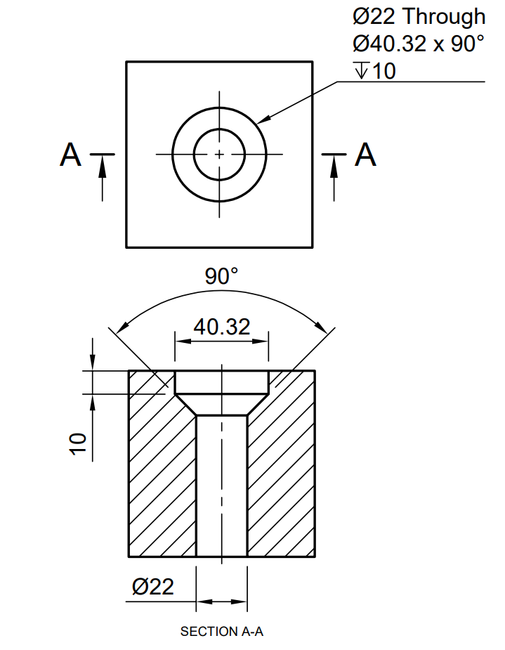
What Is the Countersink Symbol?
The symbol for a countersink is ‘⌵’.
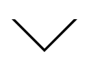
How Are Countersinks Shown on Drawings?
Countersunk holes are shown on drawings as follows – the bottom section view shows what the top dimension refers to.
If the countersink was a blind hole, the ‘Through’ above would be replaced with the depth of the pilot hole.
You may be wondering what the ‘Ø40.32′ is. This is known as the theoretical edge and this size countersink is for an M20 countersunk bolt.
You can find out the countersunk dimension required for countersunk metric bolts here.
What Are Countersunk Holes Used For?
Countersunk holes are used for applications where a countersunk bolt or screw is required.
Like counterbore holes, countersink holes ensure the bolt or screw sit below the surface.
Counterdrill
What Is a Counterdrilled Hole?
A counterdrilled hole is like a countersunk hole but there is a recess above it.
The 3D model below shows a counterdrilled hole with the same counterdrilled hole next to it cut in half:
What Is the Counterdrill Symbol?
The symbol for a counterdrill is the same as a countersink (⌵) but there will be a depth stated as well.
How Are Counterdrills Shown on Drawings?
Counterdrilled holes are shown on drawings as follows – the bottom section view shows what the top dimension refers to.
A counterdrill can also be stated as C’DRILL or CDRILL on an engineering drawing.
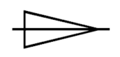
What Is the Tapered Hole Symbol?
The taper symbol is:
How Are Tapered Holes Shown on Drawings?
Tapered holes can be shown in a number of different ways on engineering drawings.
An example of a drawing showing a tapered hole is below:
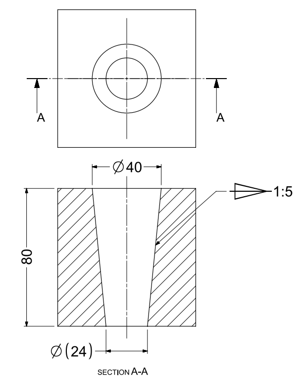
The taper in the above example is 1:5. The end diameter has been left on for reference (in brackets).
To work out what the end diameter use the equation:

![]()
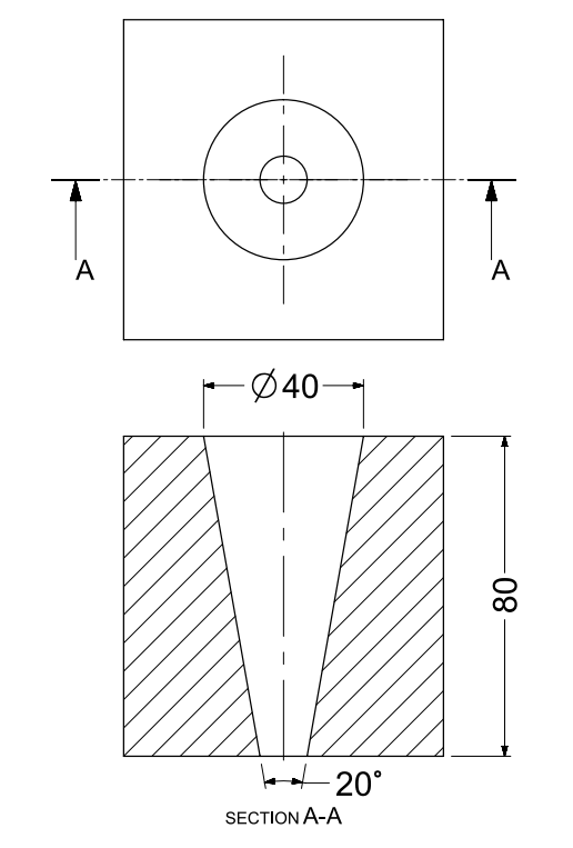
Tapered holes can also be shown without the taper symbol when dimensioning using an angle is more important:
What Are Tapered Holes Used For?
Tapered holes have lots of different engineering applications.
A common example is using a tapered hole to secure cutting tools or other tool holders.
Screw Clearance
What Is a Screw Clearance Hole?
A screw clearance hole is exactly that.
It’s a simple hole that has a slightly bigger diameter than the screw thread so that the screw can pass through.
What Is the Screw Clearance Symbol?
Screw clearance holes are shown as simple holes, and use the ‘Ø’ diameter symbol.
How Are Screw Clearance Holes Shown on Drawings?
Screw clearance holes are shown as simple holes:
What Size Screw Clearance Hole Should I Use?
You can use the metric guide for screw clearance holes or the imperial guide for screw clearance holes.
What Are Screw Clearance Holes Used For?
Screw clearance holes are used for components that need the screw or bolt to go through them.
An example of this is a bracket that needs to be attached to a block.
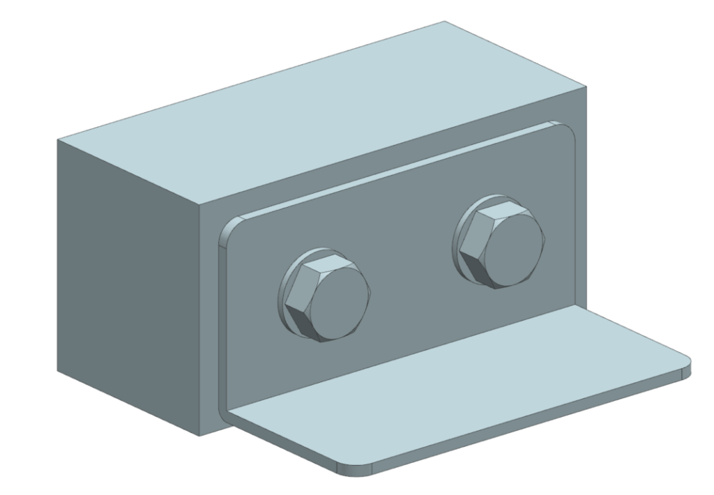
The bracket has screw clearance holes so that a bolt can pass through it.
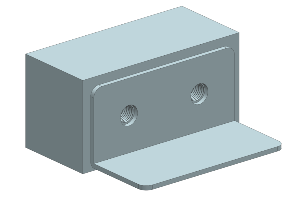
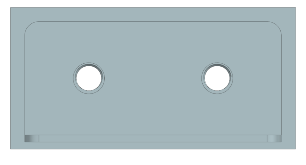
The bolt is threaded into the block which has a tapped hole.
The compression force of tightening the bolt fixes the bracket to the block.
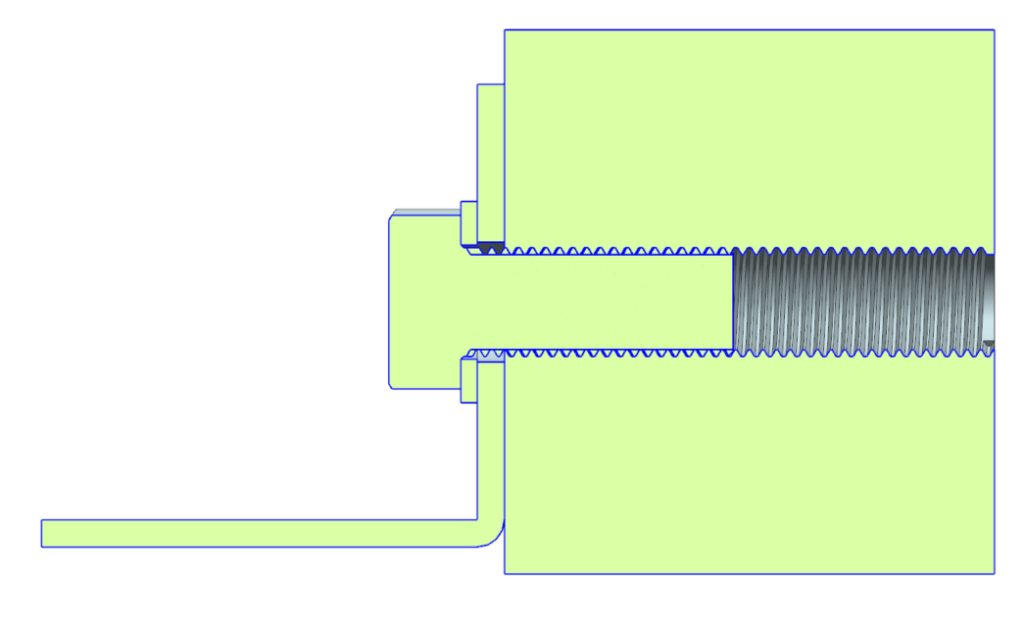
Tapped Hole
What Is a Tapped Hole?
A tapped (or threaded) hole is a hole that has a thread.
What Is the Tapped Hole Symbol?
The symbol for a tapped hole depends on the standards used. For metric holes, the diameter symbol is replaced with an ‘M’. For example a tapped hole for an M8 bolt would be ‘M8’.
For different types of threads, for example a Unified National Fine (UNF) thread, the numerical dimension is shown first then the thread type “UNF”.
How Are Tapped Holes Shown on Drawings?
Tapped holes are shown on drawings as follows:
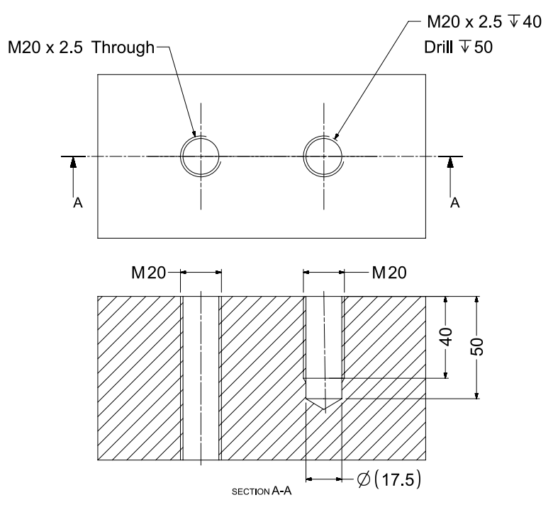
The “2.5” is the pitch of the thread, which is the distance in millimeters between each thread.
For a UNF thread, a through 1½” 12 hole would look like this:
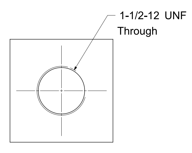
The ’12’ means that there are 12 threads per inch.
What Are Tapped Holes Used For?
Tapped holes are used to hold threaded components. Examples include screws, bolts and threaded rods.
Enjoyed this post? Check out our types of welds post.
Conclusion
We hope you enjoyed our new types of holes guide.
Now we’d like to hear what you have to say:
Which type of hole did you learn today?
Or which type of hole do you use most often?
Let us know by leaving a comment below right now.
25 thoughts on “Types of Holes – The Complete Guide”
Thanks for this info. Been a while.
Thanks John, glad you enjoyed it!
Very useful article ❤️❤️.
Very useful article!
Thanks
Thanks Valeriy!
If I have a tapped hole and counter bore feature on the periphery of a round face, would the tapped hole depth still start from the imaginary arc, or from the bottom of the counter bore? I can’t find any specific drafting standard that shows this but looking at the spot face example, it would seem that the tapped hole depth would be understood to start from the circular face, and not the first flat face at the bottom of the counter bore?
Hi Nick, great question.
Usually the smaller diameter (pilot) hole is the first dimension given for a counterbored hole, and this is the same for a hole with a spotface (i.e. the M20 hole dimension comes before the 50 mm diameter spotface dimension above).
A good way to imagine this is as if you are machining the tapped hole first and then the spotface (so the tapped hole starts at the imaginary arc in your example).
To stop any potential ambiguity in the engineering drawing of your imaginary arc example, a section view with individual dimensions for the depth could be used instead.
Is it a through hole through which cables go?
It depends on if the cables go through the whole component or not. If using electrical conduit then this pipe could be seen as a through hole for the cable.
If the cable does not go all the way through the component, such as the hole for a hotend sensor in a 3D printer heater block, then this would be a blind hole.
Thanks a lot for Detailed explain along with 3D
You’re welcome Nagma, glad you enjoyed the 3D CAD models!
what does C’Drill (Only K ) mean? please help.
Hi Tuong, C’Drill is referencing a counterdrilled hole and this article has now been updated to explain counterdrilled holes.
It’s hard to say what the ‘Only K’ is refering to without seeing the drawing. Perhaps it’s just the one instance to be counterdrilled?
Hello po ,what other term for counterdrill holes?
Hi Mello, another term for a counterdrill hole could be “C’Drill” or “CDRILL” on an engineering drawing.
We have added another 3D model to explain counterdrilled holes in more detail.
Thanks you. very well explained.
What is meaning of H7, if wirte as
“dia 16 H7 thru”
Hi Paritosh!
“H7” is the tolerance of the diameter of the hole. If using an ISO limits and fits table, this means that the final measured diameter of the hole needs to be between 16.018 mm and 16.000 mm.
Can someone explain the following?
Ø5.5±0.04 ↧ – A – (10.12)
As I understand, it means that the depth of the given hole is until datum A and than the dimension in parenthesses provides the estimated value in mm? Am I correct?
I’ve learned a lot thanks!
That’s great to hear Chris 😊
simple explanation with clear diagram.
wow this website helps me a lot at my school, thank you so much !!
Love this,thanks
Thanks