Mfr Part # BB-32621
BREADBOARD TERM STRIP 3.20X2.08"
Bud Industries
Breadboarding is an integral part of creating any electronics project.. The purpose is to set up an entire circuit using through-hole parts to ensure that its functionality is as expected prior to having a printed circuit board produced. This step saves time, money, and resources.
Let’s start with what a breadboard is. It is a solderless platform that allows for electrical connections to be made internally. The most common breadboards have two isolated sides, each with their own vertical power rails (based on orientation shown in images above) that run the length of the board. The horizontal rails (based on orientation shown in images above) are connected on each respective side and separated by a gap down the center. The center gap is perfect for placing IC’s (integrated circuits) so that each leg is electrically separated. Standard breadboards have a pitch of 0.1” (2.54mm).
The image below shows a cross section of the channels. On the left, the resistor is hooked up as a dead short because the horizontal rail connects all 5 slots. On the right the resistor is connected properly across the center divide channel.
The circuit used for this instructional guide is a “Light Theremin”. This circuit creates different pitches based on how much light is received by the photoresistor using just a few simple components. The schematic to follow is shown below.
It is good practice to begin by placing any IC’s and continue building out from there. IC’s will typically have some sort of mark or notch on them near pin 1. This specific 555 timer has a notch on one side of the IC (as shown in the schematic), while holding that notch facing left, (as shown) pin 1 is directly underneath it. Pin 8 directly above. Pin numbering on IC’s will typically start on one corner and increase around the IC counterclockwise.
Place the IC in slots 13 through 16 across the center channel as shown below. It is important when following this guide to place the components in the slots shown to prevent any shorts or other issues. Some individuals find that highlighting or crossing off components and wires on the schematic as they go helps to keep organized.
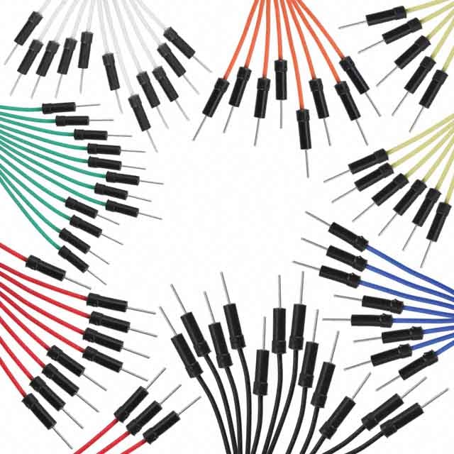
After the IC is in, it’s best to begin by placing any jumper wires or components that route directly from the IC to power or ground. Let’s start by placing the first three jumper wires shown below. For this guide, the positive power rail on the top and the negative ground rail on the bottom will be the only power rails utilized.
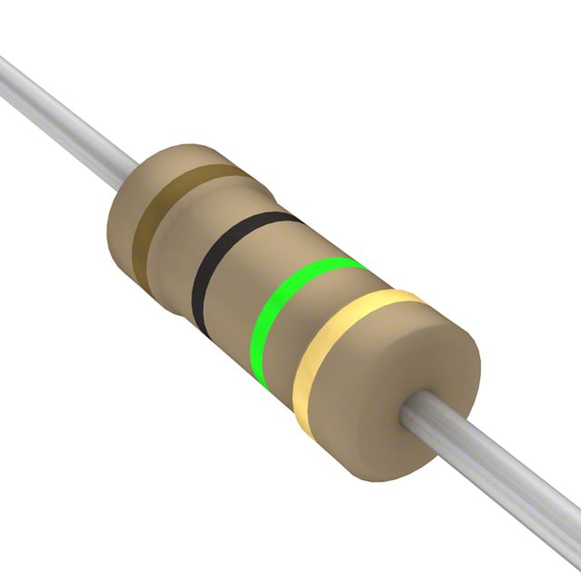
Next place the 1MΩ resistor (color code brown, black, green, gold) from A14 to ground. The orientation of this part does not matter because resistors are not polarized components.
Alright, now that all of the jumpers and components that go straight from the IC to power or ground are taken care of, let’s get into the rest of the circuit. Looking back at the schematic, the next easiest connections to make are those coming off of pin 3 on the IC.
Locate the 100µF electrolytic capacitor. Unlike resistors, this particular part is polarized so care must be taken to ensure proper orientation when placing it on the breadboard. Most radial electrolytic capacitors will have a white strip with negative symbols running along the length of the can to indicate the negative lead. Also, the negative lead is usually shorter than the positive lead. In this case the positive lead should be placed in-line with pin 3 on the IC in slot B15, while the negative lead should be placed in B23. In this case, the negative lead could go anywhere in row 17 through 30 since they are unused, but to reduce sloppiness and overlap B23 was selected.
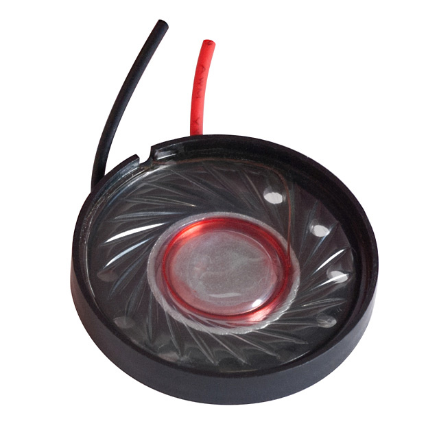
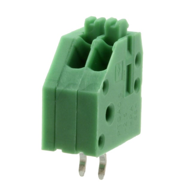
Next place the speaker leads into the green terminal block. To do this, hold the terminal with the wire leads down with the holes facing you; then press the button on top of the terminal on the right side and place the black wire from the speaker into it as far back as it will go. The button opens the hole to allow wires to be inserted. Repeat this for the red speaker lead, placing it into the left side of the terminal (see image below).
Once the speaker leads are firmly placed into the terminal, place the terminal block into the breadboard in E23 and E24. Then place a jumper from A24 to the negative power rail so it connects the black speaker lead to ground.
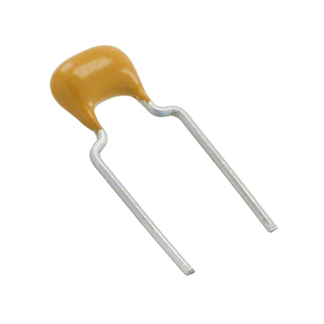
Now locate the 0.47µF capacitor. This capacitor is not polarized, so orientation is not a concern. Place the leads as shown below from A4 to the negative power rail.
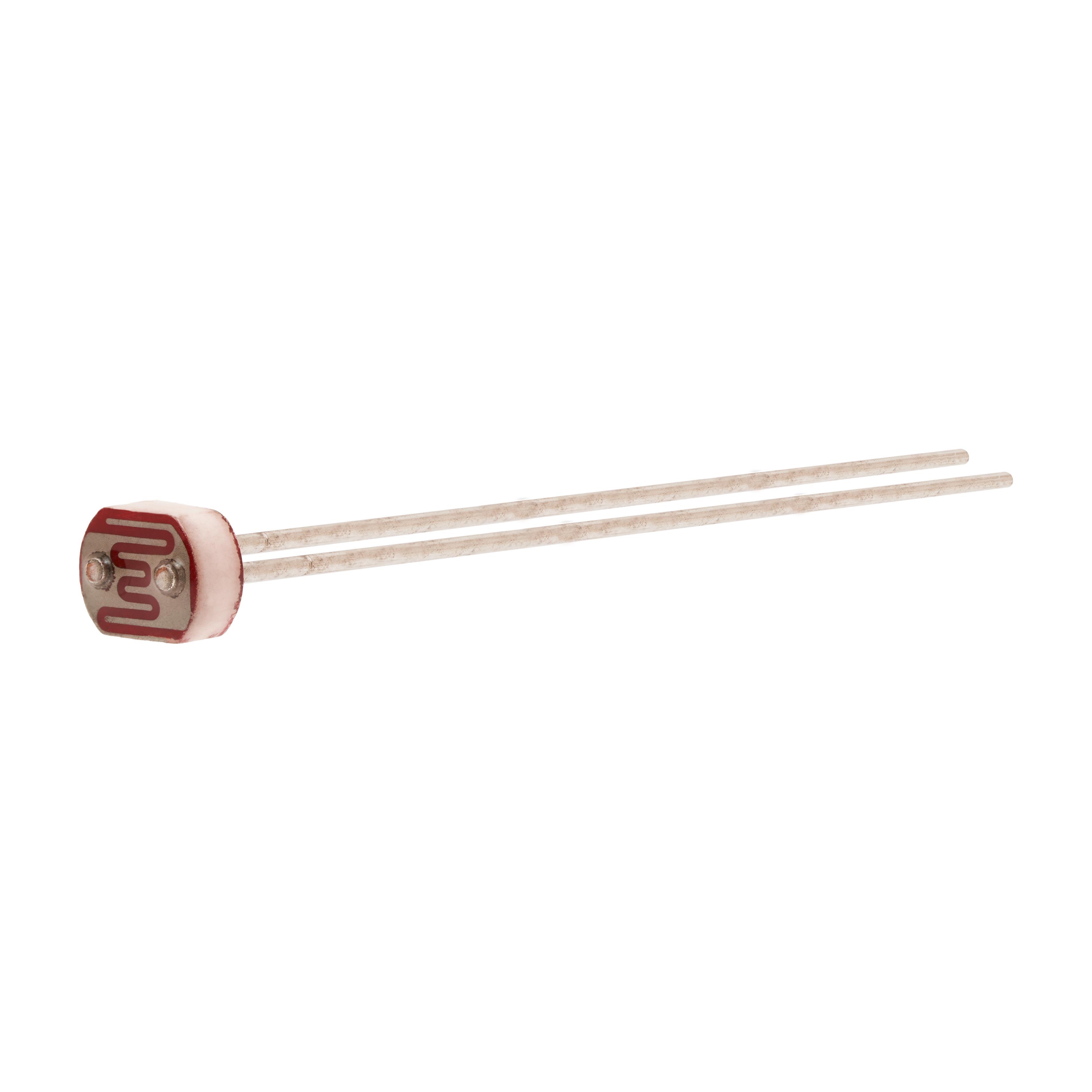
Now install the photoresistor from E4 and across the channel to F4. This part is not polarized, so either lead can go to either position.
Now let’s add the three remaining jumper wires (red, green, and blue) shown in the image below. Be sure to place them in the same positions as shown.
Locate the 10KΩ resistor (color code brown, black, orange, gold) and place it from J4 to the positive power rail.
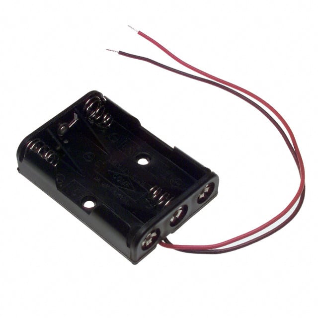
Now review the circuit one more time to ensure all the components are in the same locations that are shown in the last image. Now it’s time to test the circuit! Place the batteries in the battery holder, making sure to put them in the proper orientation, and place the red positive lead from the battery pack to the top positive power rail, and the black negative lead from the battery pack in the bottom negative power rail. See image below for a visual of this.
If there is a buzzing tone coming from the speaker, it works, congratulations! You are officially a breadboarding veteran. If it doesn’t work, re-review component positions and battery orientation and try again.
Want to take this a step further? Try trimming the component leads just enough so that they sit flush against the board, but also still insert fully into the board. Then, try cutting your own jumper wires so that they are also flush against the board. Doing this prevents components and wires from easily getting snagged and becoming disconnected from the board, ultimately preventing frustrations and giving the board an overall more polished look.

Have questions or comments? Continue the conversation on TechForum, DigiKey's online community and technical resource.
Visit TechForum United States
Copyright © 1995-2024, DigiKey.
All Rights Reserved.
Terms & Conditions
Privacy Notice
Accessibility Statement
United States
Copyright © 1995-2024, DigiKey.
All Rights Reserved.
Terms & Conditions
Privacy Notice
Accessibility Statement