2
\$\begingroup\$

The circuit for a SIM card reader is shown here. The circuit uses a CMOS hex inverter and other simple components; yet, not only does it work but it can also communicate with a PC via serial port!

I am learning electronic circuits as a hobby and I was baffled to see how simple this was. I was thinking of using some kind of micro controller for this. As you can see I am a complete amateur.

Can you please explain how this circuit works?

As a reference, here is the schematic I found on the website and is probably referred to:

SIM card reader

\$\endgroup\$
5
  • \$\begingroup\$ The link you provided is not clickable. Read up on how to properly embed tags in posts, then fix it. \$\endgroup\$ Dec 29, 2011 at 13:03
  • \$\begingroup\$ Olin wanted you to learn by doing - and it is often the best way to learn. I wanted to use the link as intened so fixed it BUT you should always check your links after positing to make sure they are OK. The problem was small but fatal. Links are of form [label stuff](URL) with no gaps between ] and (. You had a space between ] and ( so it didn't work. \$\endgroup\$
    – Russell McMahon
    Dec 29, 2011 at 13:55
  • \$\begingroup\$ Also, if you want an even easier way to put links in... just click on the link button when you are writing a post. \$\endgroup\$
    – Kellenjb
    Dec 29, 2011 at 14:14
  • \$\begingroup\$ Please note that the signal levels going out on the DB9 header are not RS232 compliant. RS232 should be (I believe) +/- 9V atleast, and this only does 0..5V (known as TTL) \$\endgroup\$
    – Hans
    Dec 29, 2011 at 20:48
  • \$\begingroup\$ Arg, this circuit doesn't even allow you to disable the clock. Kick it to the curb. \$\endgroup\$
    – Sbmeirow
    Dec 30, 2011 at 8:35

2 Answers 2

2
\$\begingroup\$

What you should ideally link to, as well as the useful top page, is the circuit diagram., as that is what you are inquiring about. It is found here

A lot of the content in your questions would be addressed by readin their FAQ well and/or by looking on web for IM card informatiin.

In their FAQ they say:

  • Is this a PC/SC-compatible SIM card interface?
    Is this a Phoenix-compatible SIM card interface?
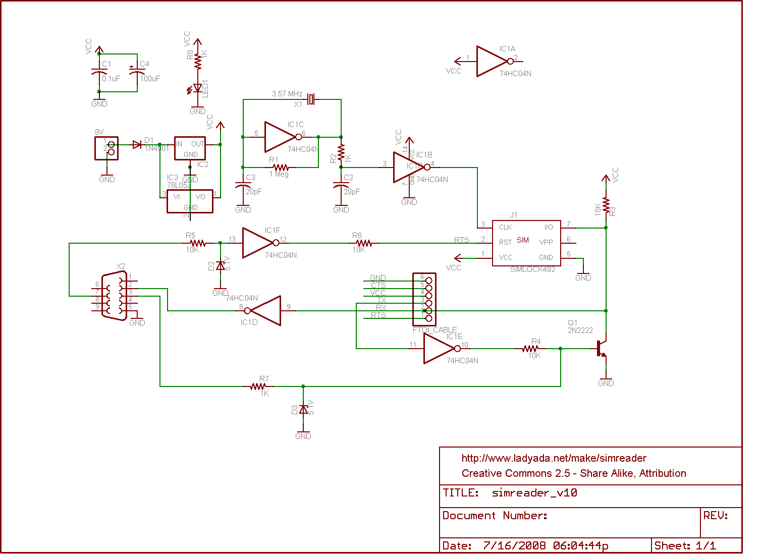
    This design uses a serial port to read and write data from a SIM. Often these are referred to as "phoenix"-type readers. PC/SC readers use a different (Windows-only) standard, and this reader design will not work with software or hardware that requires PC/SC compatibility

"Uses a serial port" and the circuit diagram should give you an immense guide.

Look at the circuit names on the SIM card.
Only on is data related, and that is named "I/O".

DATA IN:
This pin is driven by Q1. When Q1 is on the pin is pulled low.
When Q1 id off the pin is pulled high by R3.
That action allows data to be sent TO the SIM.

DATA OUT And, when Q1 is off, if the SIM toggles the I/O line then R3 will be pulled low by the SIM (Q1 has nio ffect as it is off) and FTDI-RX line and IC1d both "see" this data from the SIM.

So, that covers how data can get to and from the SIM.
The rest is a matter of specifications.
A lot on this will be in the FAQ and more via eg Gargoyle.

enter image description here

Circuit diagram: http://www.ladyada.net/make/simreader/simreaderv1_0.png

\$\endgroup\$
2
\$\begingroup\$

A SIM card has following connections:

  • Vcc and GND (power)
  • reset ("RST", input)
  • clock ("CLK", input)
  • data ("I/O", input and output)
  • Vpp isn't used in modern smart cards any more. Formerly it was supply for programming voltage.

So a smart card terminal to be used on the serial port just needs a clock generator and level shifting.
The default data rate for smart cards (ISO7816-3) is f_Clock/372.
So if the XTAL has 3.5712MHz data rate is 9600 Baud, which is one of the standard baud rates.

Reset is controlled by one of the handshaking lines.

Since the smart cards data line is bidirectional, all commands going to the card are also echoed back to the PC. This, however, can be handled by software.

However the terminal is not fully conform with ISO7816-3, because the serial data frame format for the protocol used in SIM cards (called "T=0") uses a special error bit to signal parity error detection. This signal can not be generated or handled by ordinary PC-UARTs. I.e. transmission error handling would not work.
As long as there are no transmission error this poses no problem.

If you are further interested in smart card protcols, here is a link to some ISO7816-3 informations:
http://www.cardwerk.com/smartcards/smartcard_standard_ISO7816-3.aspx

\$\endgroup\$

Your Answer

By clicking “Post Your Answer”, you agree to our terms of service and acknowledge you have read our privacy policy.

Not the answer you're looking for? Browse other questions tagged or ask your own question.