Have you ever tried to eat one jelly bean or one potato chip? It is nearly impossible. Some of us have the same problem with hardware projects. It all started when I wrote about the old bitslice chips people used to build computers before you could easily get a whole CPU on a chip. Bitslice is basically Lego blocks that build CPUs. I have always wanted to play with technology, so when I wrote that piece, I looked on eBay to see if I could find any leftovers from this 1970-era tech. It turns out that the chips are easy to find, but I found something even better. A mint condition AM2900 evaluation board. These aren’t easy to find, so the chances that you can try one out yourself are pretty low. But I’m going to fix that, virtually speaking.
This was just the second potato chip. Programming the board, as you can see in the video below, is tedious, with lots of binary switch-flipping. To simplify things, I took another potato chip — a Google Sheet that generates the binary from a quasi-assembly language. That should have been enough, but I had to take another chip from the bag. I extended the spreadsheet to actually emulate the system. It is a terrible hack, and Google Sheets’ performance for this sort of thing could be better. But it works.
If you missed it, I left many notes on Hackaday.io about the project. In particular, I created a microcode program that takes two four-bit binary-coded decimal digits and computes the proper 8-bit number. It isn’t much, but the board only has 16 microcode instructions, so you must temper your expectations. If you want an overview of the entire technology, we’ve done that, too.
Starting Point
The idea for the simulator struck me when I was building the assembler. I considered writing a stand-alone program, but I wanted to limit my potato chip consumption, so keeping it in the spreadsheet seemed like a good idea.
Was it? Hard to say. Google Sheets has macros that are just Javascript. However, the macros are somewhat slow and attaching them to user interface elements is difficult. There were plenty of ways to do it, but I went for the path of least resistance.
Strategy
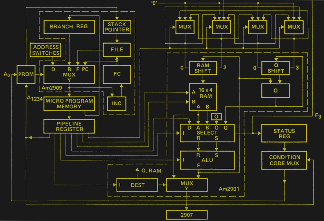
For better or worse, I tried to minimize the amount of scripting. All of the real work occurs on the Sim tab of the spreadsheet, and only a few key parts are included in the attached macros. Instead, the cells take advantage of the way the AM2900 works. For example, some bits in the microcode instructions represent how to find the next address. Instead of calculating this with code, there is a table that computes the address for each possible branch.
For example, branch type zero goes to the next address when the current result is zero or the address coded in the instruction if the result is not zero. If the branch type is one, there is always a jump to the hardcoded address, while a branch type of two always takes the next instruction. So, the associated table always computes all the possible results (see cells O1 through P18). Then, cell P18 uses VLOOKUP to pick the right row from the table (which has 16 rows).
Every part of the instruction decode works this way. The only complication is that the instructions operate on the current result, something mentioned in the last post. In other words, consider an instruction that says (in English): If the result is zero, go to location 9; add 1 to the B register. You might assume the jump will occur if B+1 results in zero. But that’s not how it works. Instead, the processor adds B and 1. Then, it jumps to location 9 if the state was zero before the addition operation.
What this means is that the spreadsheet computes all things at all times. The macros are almost like clock pulses. Instead of gating flip flops, they copy things from where they are calculated to where they are supposed to go.
Macros
The main simulation logic is in the stepengine macro. It computes the next address and sets the status latch, if necessary. Then it grabs the result of the current operation and places it in the correct destination. The final part of the macro updates the next location, which may require manipulating the processor stack. All of those things would have been difficult to do in spreadsheet logic.
The other macros are essentially wrappers around stepengine. The Exec macro executes an instruction without advancing (like stepping the real board in load mode). The Step macro can optionally single step, or it can execute in place like Exec. The Run macro does the real execution and also checks for breakpoints. There’s also a Reset macro to put everything in a known state.
Usage
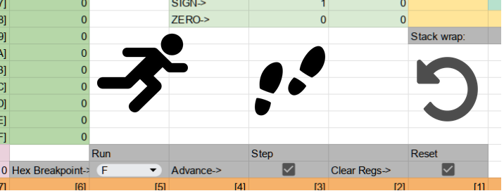
You can call the macros directly, but that’s not very user-friendly. Instead, the Sim tab has three graphical buttons for run, step, and reset. Each command has options. For example, under Run, you can set a hex address to break execution. Under Step, you can decide if the step should advance the program counter or not. The reset button allows you to clear registers.
Don’t enter your program on the Sim tab. Use the Main tab as before. You can also go to the Extensions | Macros menu to load one of the canned demos. Demo 1 is the BCD program from the last post. The other examples are the ones that shipped with the real board’s manual. If you really want to learn how the thing works, you could do worse than walk through the manual and try each example. Just don’t forget that the scanned manual has at least two typos: Figure 7 is wrong, and example 7 has an error (that error was fixed in later manuals and in the simulator’s copy, too). Instead of figure 7, use figure 3 or pick up a corrected figure on Hackaday.io.
Why learn how to operate the AM2900 evaluation board? Beats me, but I did it anyway, and now you can do it without spending the money I did on a piece of exotic hardware. I’d like to say that this might help you understand modern CPU design, but that wouldn’t be very fair. I suppose it does help a little, but modern CPUs have as much in common with this design as a steam locomotive has in common with a jet airplane.
If the idea of building a CPU from modules appeals to you, check out DDL-4. If that’s too easy for you, grab your bag of 2,000 transistors and check out this build. I’m sealing up my bag of potato chips now. Really.


“I’m sealing up my bag of potato chips now. Really.”
We’ll see!
Great article, thanks, I enjoyed that.
Now off to reopen my own bag of chips…
Thanks Fajita effect. Now I want some chips.
Now I want fajitas.
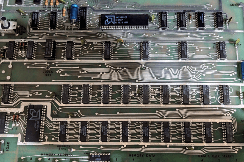
The PCB traces are beautiful (wavy, as it should be).
There also many ground traces surrounding the ICs.
That’s how a professional design should be.
Things like this show how much more thought was spent on tech in the 1970s.
1. The “wavy” traces have no positive effect, they are merely a side effect of doing layout by hand with tape.
2. There’s no ground plane on the PCB – it’ll radiate like crazy. It only works because 1970s stuff was relatively slow (a few MHz at most) and because the FCC hadn’t gotten around to clamping down on unintentional radiators (or because the whole thing was in a grounded metal box to keep all the crap in.) The ground traces are an attempt to make up for the lack of a ground plane.
3. Decoupling capacitors are few and far between – any modern engineer would catch hell for that. The lack of decoupling capacitors will make the entire circuit susceptible to glitches.
why 8 bits? not 10 bits?
Because the AM2900 is a 4-bit bitslice device. The wordlength must then be a multiple of 4.
Fun to see. As a new EE I designed a frame buffer for a video display and programmed the 2900 based GPU to test the buffer. The display was 16 level monochrome CRT, 60Hz 2048×1536 – in 1983. Unfortunately never made it to market.
In the early 80’s we used bitslice technology and a couple gate arrays to process scanned 35 mm film. Required a 400A 5V supply.