In this article, you’ll learn what is coupling? Definitions, types of shaft coupling, how to use? parts, application, and diagrams.
And also you can download the PDF file of this article at the end of it.
Coupling and Types
What is coupling?
A coupling is a device that is used to connect two shafts together for power transmission. Couplings are rigid or flexible according to the alignment accuracy and torque requirement.
What is shaft coupling?
The shaft coupling is a mechanical component that connects two rotating shafts such as the driving shaft and driven shaft for purpose of transmitting power. It is used in motors, pumps, generators, and compressors.
How does a Shaft Coupling Work?
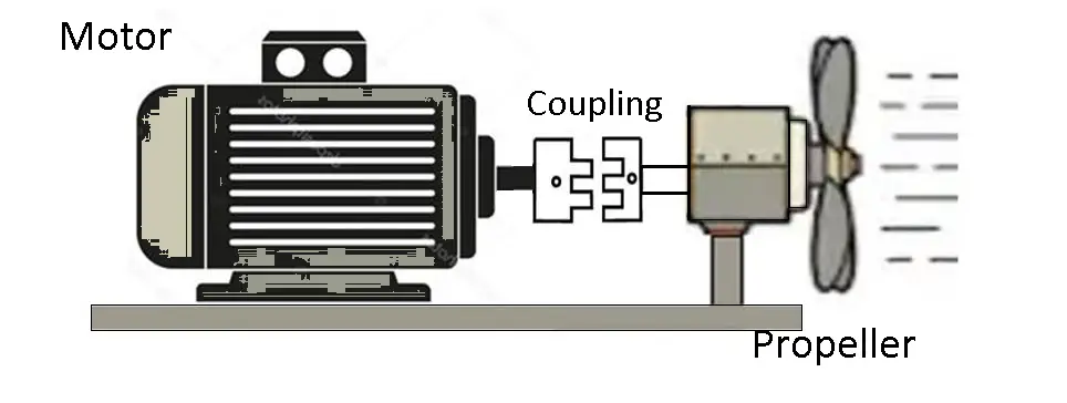
You can connect two shafts together by coupling as shown in the above diagram. No problem if the shaft diameter is different.
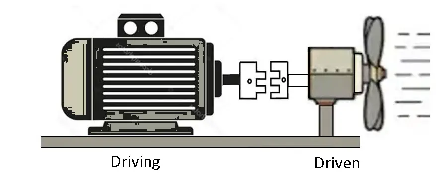
As per the above diagram, the motor is the driving side, and the propeller is driven side.
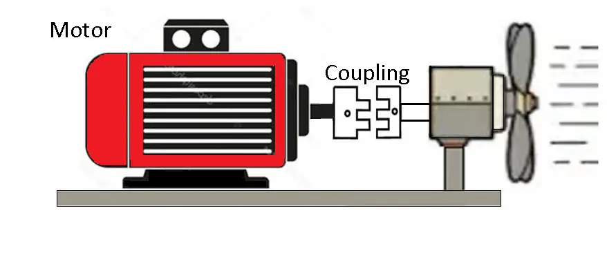
The coupling does not transfer the heat etc. of the motor to the driven side.
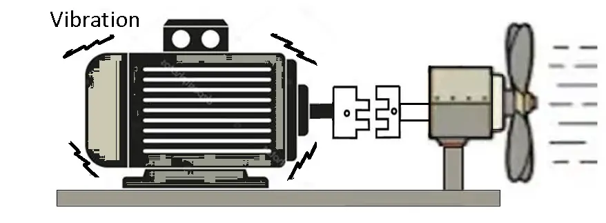
Coupling absorbers the shock and vibration from transferring, this will help to protect surrounding components from damage.
Read Also: What are the different types of furnaces? [PDF]
Why Shaft Coupling is Used?
Following are some of the most common reasons why shaft coupling is used:
- Used to connect shafts of units that are manufactured separately such as a motor and generator.
- For the misalignment of the shafts.
- For mechanical flexibility.
- Absorbs the transmission of shock loads from one shaft to another shaft.
- Protection against overloads.
Types of Coupling
Following are the different types of coupling:
- Rigid Coupling
- Sleeve or muff coupling.
- Clamp or split-muff or compression coupling, and
- Flange coupling
- Flexible coupling
- Bushed pin-type coupling,
- Universal coupling
- Oldham coupling
- Gear coupling
- Bellow coupling
- Jaw couplings
- Diaphragm couplings
- Fluid Coupling
- Constant speed coupling
- Variable speed coupling
#1 Rigid Coupling
A rigid coupling is used when two shafts are perfectly aligned. These are only suitable in close alignment. Ex. Sleeve or muff coupling, Split-muff coupling, and Flange coupling.
#2 Sleeve or Muff Coupling
Muff or sleeve coupling is the simplest type of rigid coupling, this is made up of cast iron.
Construction:
Muff coupling consists of a shaft, key, sleeve, or muff, and a hollow cylinder whose inner dia is the same as that of the shaft. It is fixed over the ends of the two shafts with the help of a gib head key.
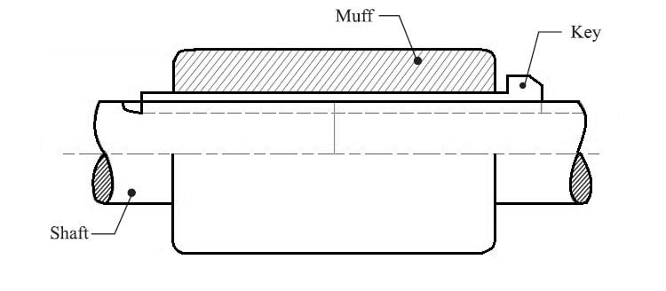
The power transmission is done from one shaft to the other shaft by means of a key and a sleeve. It is necessary that all the elements must be strong enough to transmit the torque.
#3 Clamp or Split-muff or Compression Coupling
It is also known as split muff coupling. In these typse of couplings, the muff or sleeve is made into two halves and is bolted together. The halves are made of cast iron. They are connected together by means of studs or bolts.
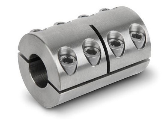
Both shaft’s ends are connected to each other and a key is fitted in the keyway of the shafts. One end of the muff is fixed from below and the other end is attached from above. Both are held together by bolts and nuts.
This coupling is widely used in heavy-duty speeds. There is no need to change the position of the shaft to assemble or disassemble the coupling.
#4 Flange Coupling
It consists of two cast iron flanges which are fixed at the end of each shaft. The two flanges are bolted together with bolts to complete the drive. A flange coupling is to bring two tubes together in a sealed manner.
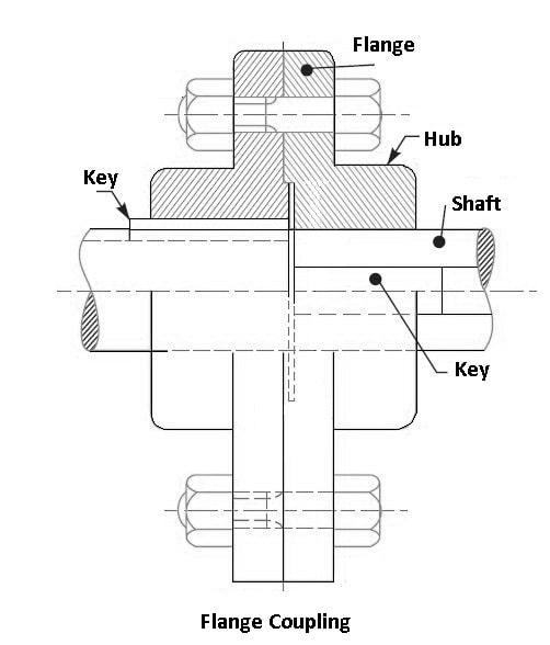
One of the flanges has a projected portion part and the other flange has a similar recess. Each flange end is bought together to make correct alignment without causing resistance in the material being passed through them.
It helps to bring the shaft into the same line and to maintain alignment. The two flanges are coupled together by means of nuts and bolts. These couplings are typically used in pressurized piping systems. Also, it is employed for heavy loads hence, it is very beneficial on large shafting.
Following are the three different types of flange coupling:
- Unprotected type flange coupling.
- Protected type flange coupling.
- Marine type flange coupling.
#5 Flexible Coupling
It is used to connect two shafts that have both lateral and angular misalignment. Ex. Bushed pin-type coupling, Universal coupling, Oldham coupling, Gear coupling, Bellow coupling, Jaw couplings, Diaphragm couplings.
Read Also: What is Woodruff Key? How does it work? [PDF]
#6 Bushed Pin-type Coupling
This is used for slightly parallel misalignment, angular misalignment, or axial misalignment of the two shafts. It is a modification of the rigid flange coupling. It consists of two halves that are dissimilar in construction and bolts known as pins, rubber bushes which are used over pins.
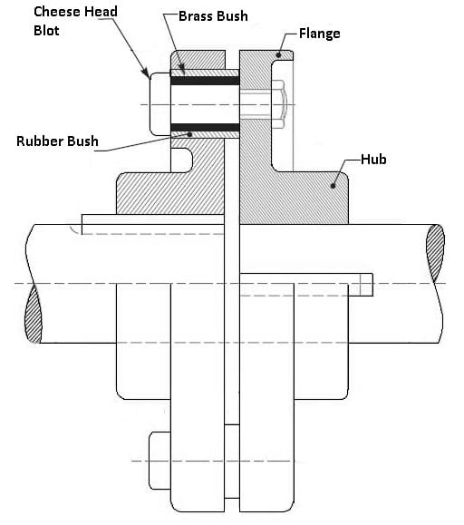
There is a clearance of 5 mm between the faces of the two halves of the coupling. There is no rigid connection between them and the drive done through compressed rubber or leather bushes.
#7 Universal Coupling
The universal coupling is also known as Hooke’s coupling. It is used when two shafts’ axis intersects at a small angle. The inclination of two shafts can be constant, but in actual practice, this changes when the motion is transferred from one shaft to another.
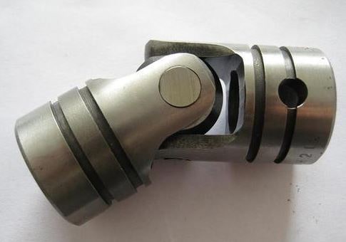
A universal joint is shown in the above figure. These couplings are widely used in the transmission of power. Universal coupling is found in the transmission from the gearbox to the differential of the automobile. In these cases, two universal joints are used on each end. One at the end of the propeller shaft to the gearbox and one on the differential to another end.
Universal coupling is also used for the transmission of power to different spindles of multiple drilling machines and milling machines.
#8 Oldham Coupling
Oldham coupling used where two shafts have a lateral misalignment. The below figure shows the schematic diagram of Oldham coupling. As a figure, it consists of two flanges A and B with slots and a middle floating part E with two tongues T1 and T2.
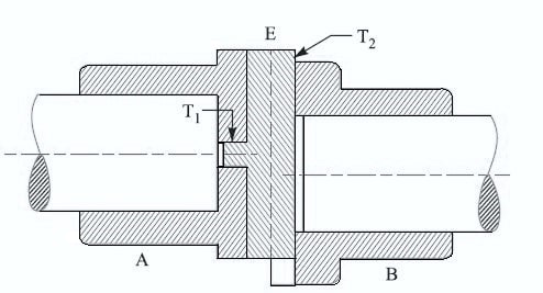
The middle part is fixed by means of pins that are fitted to flanges and floating parts. The T1 tongue fits into flange A allowing back and forth motion and T2 is fitted into flange B and allows for vertical motion of the parts.
These two components of speed will result in the lateral misalignment of the shaft being adjusted as they rotate.
#9 Gear Coupling
The gear coupling is a modified version of the flange coupling. Gear couplings can transmit high torque because of the large size of the teeth. In this types of shaft coupling, the flange and hub are separately assembled together instead of as a single part as flange coupling.
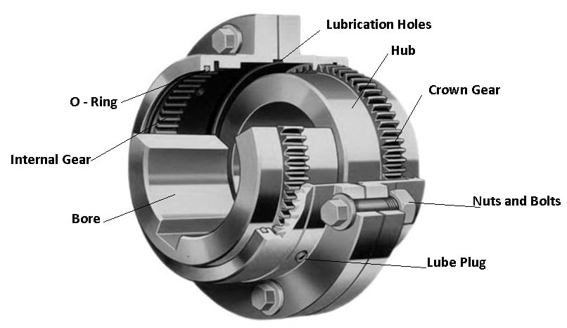
In construction, each joint has a 1:1 gear ratio internal and external gear pair. And gear coupling is limited to angular misalignments about 0.01-0.02 inches in parallel and 2 degrees in angular.
Gear couplings and universal joints are used for similar applications. These are mostly used in heavy-duty applications where the torque transmission is required to be high.
#10 Bellow Coupling
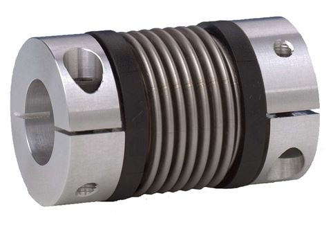
Bellows couplings are flexible coupling with twin coupling ends called hubs. These couplings have excellent torsional rigidity to accurately transmit velocity, angular position, and torque. They are usually made up of stainless steel. These couplings are used where high precision positioning is required.
Bellows coupling consists of thin walls and has minor flexibility angular, axial, or parallel misalignment. The hubs are welded to the coupling bellow. These couplings have the highest torsional stiffness of any servo motor coupling.
Read Also: Different Types of Metals and Their Properties [PDF]
#11 Jaw coupling
This coupling is used for general purpose power transmission it is also used in motion control applications. Jaw coupling is designed to transmit torque while reducing system vibrations and adjusting misalignment, which protects other components from damage.
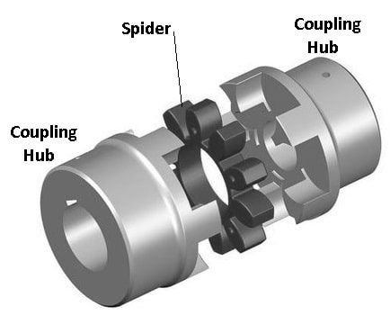
Jaw coupling consists of two metallic hubs and an Elastoplast insert called an element, also known as “spider”.
Following are the advantages of Jaw Coupling:
- This system can handle angular misalignment and reactionary loads due to misalignment.
- Has a good torque to outside diameter capability.
- Good chemical resistance and decent dampening capability.
#12 Diaphragm Couplings
Diaphragm couplings are one of the nonlubricated couplings used in high-performance turbomachinery, transmitting torque and serving misalignment between equipment shafts.
This type of coupling transmits torque from the outside to inside diameter, and then from inside diameter to outside diameter.
Diaphragm couplings uses a single or a series of plates for the flexible members. Diaphragm coupling allows angular, axial, or parallel misalignment. This coupling is used where high torque and high speed required.
#13 Fluid Coupling
A fluid coupling is also known as hydraulic coupling. It is a hydrodynamic device used to transmit rotating mechanical power through the acceleration and deceleration of hydraulic fluid. It is consists of an impeller on the driving shaft (input) and a runner on the driven shaft (output). The impeller act as a pump and the runner acts as a turbine.
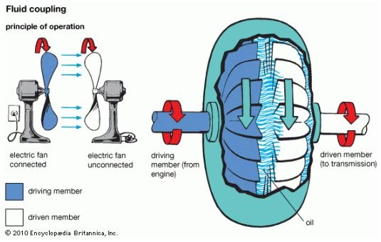
In the impeller near its axis, the tangential component of absolute velocity is low. where on its near periphery the tangential component of absolute velocity is high, therefore when the impeller accelerates the fluid velocity increases.
An increase in velocity also increases kinetic energy. The fluid emerges at high velocity from the impeller, strikes the runner blades, transfers its energy, and leaves the runner at low velocity.
Conclusion:
So, that’s it. I think you have understood everything about “what is shaft coupling and types of coupling” but still, if I missed something or if you have any questions to ask you comment or contact me through email I’ll respond to you.
Subscribe to our newsletter to get notifications of our latest articles.
Download PDF of this article:
You may be interested in reading these:
- Power Steering System: Types, How does it work?
- What Is Hydramatic Transmission or Fully Automatic Transmission? How did It work?
- Overdrive Transmission: How It Works?
External Links:
Dear sir,
I need types of coupling PDF.
THANKS & REGARDS
N.BHUVANESH
You’re welcome. The PDF file has been sent to your inbox.
Thank you so much, for this type of information. But pdf can’t download sir…..
You’re welcome. The PDF file has been sent to your inbox.
Sir
Please send me the PDF
The PDF file has been sent to your inbox.
thank you very much
You’re welcome.
The information is very fruitful and helpful. Thanks for sharing it.
You’re most welcome. Keep visiting 😉
Thanks so much, very helpful.
You’re welcome.
Thanks a lot for the clear presentation.
Im glad it was helpful for you.
Thank you for the clear information about the couplings
You’re welcome. Keep visiting 🙂
Sir i want to download this pdf. But can’t download it, please help me how to download this pdf
I just sent you the PDF file of this article to your inbox.
Sir i want to download this pdf. But can’t download it, please help me how to download this pdf
I just sent you the PDF file of this article to your inbox. Please checkout.
Hi can you send me also the pdf of this..it is useful and knowledgeable
Thanks for your feedback. The PDF file has been sent to your inbox.
You need to add our coupling to your list
Sure, I will update the article.
A great blog with very much detailed information. Helped me a lot. Thankyou.
Glad you liked it. You’re welcome.
Preparing for my trade test, useful. Where can I get more of this ?
We have tons of articles on our website. Please checkout.
Sir i want to download this pdf. But can’t download it, please help me how to download this pdf
I just sent you the PDF file of this article to your inbox. Please checkout.
Really great sir
Thank you so much:)
Sir how do I download the Pdf file? Your article is a great help to my study…
You can download the PDF file by clicking on the download button at the end of the article.