
Abstract
The aim of our research is to mobilize a new system for managing and reusing rainwater, using alternative techniques to help save water and secure the supply of drinking water, without wasting it. To this end, our study focused on rainwater collection, storage, treatment and distribution to the various users, in compliance with current standards for reuse, based on these alternative techniques and using EPA SWMM5 modeling software. A case study was carried out on Zone 1 of the Settat university campus, covering an area of 6.56 Ha, with an intense rainfall of 42 mm/h for 30 min and an average annual rainfall of 372 mm/year. The result obtained is very significant, with a yield of up to 90%: i.e. rainwater collection of 334. 8 L/m2/year, i.e. 21 963 m3/year, stored at rainfall in tanks with a total capacity of 1 336.20 m3, to be reused for flushing toilets, irrigating gardens and green spaces around the study site, thus saving on drinking water consumption, a significant gain and also savings on investment and on the operation of on-site and off-site rainwater works. In conclusion, within a limited surface area, the use of alternative techniques for managing and reusing rainwater leads to a saving of over 50% in drinking water, and it is hoped that this will provide solutions that will enable man, farmland and industry alike to alleviate water stress, cope with the shortage and scarcity of water resources, secure and save drinking water and combat wastage in the future.
Keywords
1 Introduction
Water is at the heart of the major challenges facing the potential impact of climate change and seasonality on the frequency and spatial and temporal distribution of precipitation [1]. With population growth and climate change, the water supply processes of many of the world's cities are being put to the test, to solve this problem, many researchers, water managers and watershed authorities are adopting a number of solutions and measures, including water demand management and the identification of alternative water resources, such as rainwater harvesting, seawater desalination, and the reuse of grey water and treated wastewater. Of all these alternative water resources, rainwater harvesting has received the most attention. It's important to note that rainwater is a free source and can be collected in considerable quantities from roofs, gardens, sidewalks, pavements, green spaces and parking lots, and can be reused for drinking, washing up and bathing, all with proper treatment the researchers [2] have demonstrated that rainwater harvesting for drinking and domestic needs is possible, where the issue of unavailability or insufficient potability on the water supply, rainwater harvesting and storage can be part of the solution, and particularly reuse in non-potable uses after filtration and proper treatment (for example: watering gardens, green spaces, golf courses, toilet flushing, laundry, vehicle washing, cooling and heating). Rainwater collected from roof runoff or other receiving surfaces is the most common type of RWH system, as it requires minimal treatment and consists only of a collection area, a conveyance system and a storage tank [3,4,5]. The quality of rainwater collected and stored depends on the cleanliness of the collection surface (roof, sidewalks and pavements); a significant improvement in rainwater harvesting (RWH) quality is achieved by using an inlet and outlet filter in relation to the storage tank [6]. Rainwater harvesting can therefore play an important role in water sustainability and in reducing pressure on drinking water supplies, given the water scarcity experienced in recent years in many regions. Numerous studies have reported significant water savings in a building through the use of a rainwater harvesting system [3, 5, 7].
Today, this RWH technique is strongly encouraged and promoted in Australia, Great Britain, Germany, the United States, Brazil, Japan, China and in India, and is also beginning to gain ground in other parts of the world. The benefits of rainwater harvesting as a complementary or alternative means of urban water supply have been demonstrated by numerous researchers. For example, it has been reported that rainwater promotes significant savings in potable water consumption in buildings. The researchers [5] studied water savings from large underground rainwater tanks (110 kL and 185 kL) over one year and found total water savings of around 400 to 740 kL. In South Australia, Imteaz et al. [8] confirmed through their study in Melbourne, Australia, that there is a linear relationship between annual rainfall and rainwater tank volume. This is also supported by Rahman et al. [9].
Imteaz et al. [5] demonstrated that for a two-person household scenario, around 100% reliability can be achieved with a 150–300 m2 roof and a 5 000–10 000 L tank, Rahman et al. [9] also studied that a 5 kL tank is preferable to 2 kL and 3 kL tanks and that rainwater tanks should be connected to toilets, laundry and outdoor irrigation to achieve the best financial outcome for homeowners, and assessed the financial viability of a RWH in Sydney to provide advice to water authorities to improve the acceptance of a RWH.
The results found by numerous researchers, makes it clear that, without an RWH system, the rain that falls on the surface of an area will be lost without being recovered or reused, while drinking water is still consumed and wasted for watering green spaces, gardens and golf courses, for cleaning floors and washing vehicles, and why still flush toilets and wash clothes from buildings’ drinking water networks? And since drinking water has become so precious in recent years, this article presents a suitable solution through the development of a new RWH technique, as well as its management and enhancement through the use of alternative techniques (AT), appropriate approaches, tools and data, with gravel and gravel drainage and DN 200–315 perforated PVC nozzles, particularly on the most adjacent gardens, this technique ensures freshwater drainage, increasing the release of RWH and eliminating pollution as far as possible by reducing run-off (because this hydraulic aspect, with more impermeabilization, rakes up more matter and debris existing in the soils crossed by rainwater) for efficient, cost-effective reuse, in compliance with current standards.
Our case study is carried out at the Campus of Hassan Premier University in the city of Settat, Morocco, and improves and reinforces previous studies carried out by several researchers on building RWH systems, taking into account hydrological and hydraulic principles and assumptions.
In comparison with our case study of the Hassan Premier University campus in Settat, using alternative techniques for collecting rainwater from gardens (with gravel drainage and perforated nozzles), pavements and roofs, resulted in a saving of over 50% on the drinking water bill, taking into account the high purchase price, Our result is far superior to that found on the ARIZONA university campus. This RWH technique using TAs has enabled the collection of 21 963 m3/year over a surface area of 65 600 m2, i.e. the collection of 335 L of water per m2 of surface area per year, which is even higher compared with previous RWH studies [1, 5, 9] which found an average of 100–250 L/m2/year.
2 Methods and Supports
2.1 Definition and Description of the Case Study Area
The study area is defined in zone 1 of the Hassan Premier University campus in the town of Settat, Morocco, with a surface area of 65 600 m2 (see Fig. 1). The Lambert (X, Y) coordinates of this zone are: (292 786, 269 230), for altitudes, see the profile analysis and review below.

Presentation of three longitudinal profiles and four cross-sections, in the defined study area in University Hassan first in Settat
2.2 Rainfall Data and Corresponding Analysis
With regard to rainfall data, which are collected from Morocco-Weather-management, the average annual rainfall for the city of Settat is 372 mm, winter in this city is characterized by higher rainfall, with a maximum of 66 mm in December, a minimum <1 mm in August and July, and an average monthly rainfall of 53 mm.
For the sizing of rainwater collection structures, we will use data from the Direction de Morocco-Weather, which has established Intensity–Duration–Frequency (IDF) rainfall curves at the Casa-Anfa station (for the period 1960–2013 (data adapted to the study area). These IDF curves were established on a 5-min time step for return periods of 2, 5 and 10 years. The corresponding Montana coefficients (see Table 1), used in the formula:
Are well-known: formula in hydrology, among hydrologists and hydraulic engineers, which is a function of the safety of the structure to be dimensioned, these coefficients for the Settat region are shown Table n°1 below:
For a return period T, the risk or probability of exceeding the design flow Q (T) is 1/T, for T = 2 years the risk is 50 and 20% for T = 5 years. In our study, for greater safety in the design of storm water treatment facilities, we will take a return period of 10 years, that is to say, a risk of overrun equally to 10%, it's favorable to low risk of exceeding the design flow.
The duration of the project rainfall must be greater than or equal to the total time of concentration of the study area. These concentration times will be calculated for each of the drainage basins from which the network and the rainwater harvesting (RWH) structures will be calculated or sized. It is an intense period of 30 min, which leads to a rain of intensity 42 mm/h laying a duration of rain taken equal to 3 h. The rain-flow transformation is done in two steps: Calculation of net rain; And the transformation of the rainfall into the flow is noted on the hydrograph which mentions the peak flow of dimensioning allowing more safety about the overflows and the floods.
2.3 Topography of the Study Site
The detailed knowledge of the topographic profiles is very necessary for the tracing suitable for proper tracing the framework of the gravity sewerage network allowing a more profitable and more efficient of RWH, for this purpose, we have appropriately designated on the surface of the study area (65 600 m2 = 410*160 m2), three profiles along and four cross-sections (see Fig. 1).
-
The three (3) longitudinal profiles are taken over a length of 388 to 410 m, in which the elevations vary respectively between a minimum of 325.8 m, a maximum of 345.4 m, and an average with an average of 333 m, thus presenting a height difference of 20 m, i.e. a slope of about 5% and an average of 333 m.
-
Four (4) cross sections are taken over a width of 151–160 m, in which the elevations vary respectively between a minimum of 325.8 m and a maximum of 347.2 m, thus presenting a height difference of 21 m, i.e. a slope of approximately 13% and an average of 334 m. So with these profiles presented above, very particular attention must be paid to the layout of the trace of the RWH network.
2.4 Basic Approach, Simulation, Design, and Hydraulic Balance by Using the EPA-SWMM Software
3 Alternative Techniques
We thought about enriching and strengthening rainwater harvesting (RWH) through alternative techniques (AT), which consists of increase and strengthen the performance of the valuation and the RWH. There are several types of alternative techniques “from Memento_technique_2017_Astee.pdf”, seven of which we will use in our case study (see Fig. 2), and which are generally the most suitable: (1) a non-vegetated storage roof, (2) a rain barrel, (3) a rain garden, (4) a bio-retention cell (5) a valley or landscape ditch, (6) an underground basin or reservoir, (7) an infiltration well.

Most suitable alternative techniques in our research
Collection and Recovery of Rainwater by Alternative Techniques
The RWH by the use of AT also makes it possible to ensure the sustainability of the ecosystems concerned, for example, by ensuring groundwater recharge via the aforementioned infiltration wells. The RWH is generally made up of five elements:
-
a.
A catchment area/collection area which produces runoff water from an impermeable surface or low infiltration surface, drainage, including the various alternative techniques aimed at collecting a maximum of rainwater (90%), by the seven ATs outlined above, which are the most suitable.
-
b.
A conveyance system in which runoff is directed via gutters, pipes, bunds, ditches, channels and gullies.
-
c.
A drainage system, in the case of natural terrain, gardens or green spaces, combining retention, infiltration and drainage by filtering runoff via gravel pack drains 25–30 cm thick and perforated PVC nozzles with 200–315 mm in diameter, directed towards the underground storage tank (see illustration in Fig. 3).
Fig. 3 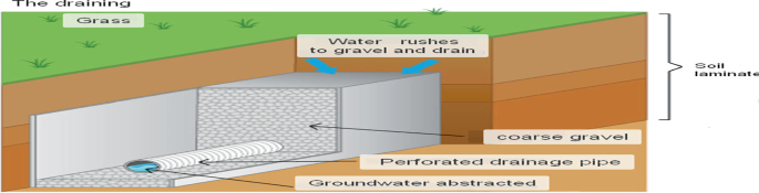
illustration of drainage through gravel pack and perforated nozzles
-
d.
A storage system, where the water is accumulated and made ready for use, in the form of underground tanks or small dams (when the maximum level is reached, the surplus can be evacuated via an overflow to an infiltration well in the ground to recharge the water table).
-
e.
An application zone where the collected water will be reused, after treatment complying with current standards, for (watering gardens, flushing toilets, washing clothes, cleaning the ground, washing vehicles, drinking, bathing, washing up, watering green spaces or golf courses, irrigating farmland, agricultural production and also for supplying industries).

Hydraulic Balance, Simulation and Design by EPA-SWMM-5.1
The EPA-SWMM5 model «UsersGuideToSWMM5Edn13.pdf Also available: Rules for Responsible Modeling. William James, 2003, 300 pp. ISBN: 0-9,683,681-5-8, 2003: On ligne available on the website: www.chiwater.com», a dynamic rainfall-runoff simulation software package, was used to process, simulate and design the water balance, from precipitation, infiltration and runoff through to storage of storm water in underground basins or reservoirs via ATs. It can be used to model the quantity of storm water for a one-off or long-term event.
There are several models for the rainfall-runoff transformation. In the nonlinear reservoir model used by the EPA-SWMM-5.1 software.
A very detailed study and analysis has been therefore carried out with the aim of collecting, storing, treatment and distribution, in compliance with current usage standards, and on the basis of the hypotheses mentioned above, using modelling software to solve the various mathematical and physical problems associated with the hydrostatic and hydrodynamic state of storm water in relation to the data, constraints and characteristics of urban planning, economics, hydrology, climate, hydrography and topography to optimize and size the pipes and structures required for well-defined areas and basins, taking into account the alternative techniques mentioned above.
The case study of the Hassan Premier University campus area in the town of Settat in the country of Morocco, over an area of 6.56 ha, assuming a project rainfall of 30 min “intense rain”. i.e. an intensity of 42 mm/h according to the aforementioned Montana formula and with an average annual rainfall of 372 mm/h in the Casablanca-Settat region (collected from the Morocco-weather department).
4 Results and Discussions
The case study taken on the study area at the Settat University Campus (see Fig. 4), is taken in two scenarios presented as follows, taking into account rainfall data, topographic and land surface characteristics, using EPASWMM software and Google Earth platform, as presented below in part 2 (method and material), led to the following results.

Scenario1_RWH by sub-catchment and the on-site network with a single outlet for discharge into Oued _ without the use AT
Scenario n° 1: The trace of the on-site network and storm water drainage sub-basins with a single R16 outlet (see Fig. 4), without the use of AT.
In Scenario n°1, the peak flow (see Fig. 5) is 690 L/s, reached at collector section C15 = R15-R16 (see Fig. 4) after half an hour of 42 mm/h rainfall, passing through manhole R16 to reach the 600 mm diameter off-site pipe, which then carries the storm water over a total length of 930 m to Oued Boumoussa.

Scenario1_Hydrogram of flow at single outlet R16_without AT _ in the university campus of Settat
Longitudinal profiles R1-R16 and R10-R16 shown in Figs. 6 and 7, with pipe diameters from 315 to 600 mm, with the maximum storm water filling level at time t = 30 min, i.e. after half an hour of rainfall, during which the maximum flow rate of 690 L/s is reached.

Scenario1_Longitudinal profile R1-R16 with fill level at peak discharge

Scenario1_Longitudinal profile R10-R16 with fill level at peak discharge
The volume of rainwater collected is calculated by integrating:
Approximate by
\(\mathrm{with}\;\Delta t=1 s,\) i.e. one second step.
Based on the EPASWMM software's rain-flow transformation (see flow hydrograph in Fig. 5), we find a total water volume of 1 265.10 m3, collected and conveyed by on-site pipes with a total linear length of 1 495 m in DN 200, 315, 400, 500 and 600 in PVC S1, and off-site pipes with a linear length of 930 m in diameter 600 mm in PVC S1.
With an overall cost of 0.30 Million USD including operation and maintenance of on-site and off-site networks in the study area,
i.e. Overall amount/surface = 0.30 Million USD/65 600 m2
i.e. 4.6 USD/m2
In this Scenario n°1, the collected rainwater, with a volume of 1 265.10 m3, is channeled from manhole R16 through the off-site area for discharge into Oued Boumoussa, continuing its journey and being lost in nature towards the sea (Atlantic Ocean) without recovery or reuse, and with a major investment of 0.30 Million USD with no return on investment?
Scenario n° 2: The trace of the on-site network and sub-watersheds for RWH with two outlets, R19 and R20 (see Fig. 8), using AT, to manage and recover rainwater for reuse after treatment, by storing it in three (3) underground tanks, thus recovering the investment through this recovery.

Scenario2_RWH by sub-catchment and the on-site network with a two outlet_ with TA, and storage in underground tanks
In Scenario n° 2, the design and result differ, with two outfalls R19 and R20 (see Fig. 8) chosen, but no off-site discharge to the Oued Boumoussa, with the aim of storage in three suitable tanks and then reuse for different purposes after proper treatment.
According to Fig. 9 for outlet R19, the peak flow rate of 134 L/s is reached at collector section C18 = R18-R19 (see Fig. 8), with pipe diameters from 200 to 600 mm, after half an hour of rainfall of 42 mm/h, passing through manhole R19 for storage in reservoir n°1.

Scenario2_Hydrogram of flow at outlet n°1 = R19_ with AT _in the university campus of Settat
The R12-R19 longitudinal profile shown in Fig. 10, from 315 to 600 mm diameter, with the maximum storm water filling level, at time t = 30 min, i.e. after half an hour of rainfall, during which the maximum flow rate of 134 L/s is reached.

Scenario2_Longitudinal profile R12-R19 with fill level at peak discharge
The volume of storm water collected is calculated in the same way as in scenario n°1, by integrating:
Approximate by
\(\mathrm{with}\;\Delta t=1 s,\) i.e. one second step (see flow hydrograph in Fig. 9), we find an overall water volume of 234.60 m3.
And according to Fig. 11 for outlet R20, the peak flow of 620 l/s is reached at collector section C19 = R10-R20 (see Fig. 8), with pipe diameters from 200 to 600 mm, after half an hour of rainfall of 42 mm/h, passing through manhole R19 for storage in reservoirs n°2 and 3.

Scenario2_Hydrogram of flow at outlet n°2 = R20_with AT _in the university campus of Settat
Longitudinal profile R1bis-R19 shown in Fig. 12, diameter 315 to 600 mm, with maximum rainwater filling level, at time t = 30 min, i.e. after half an hour of rainfall, during which time the maximum flow rate of 640 L/s is reached.

Scenario2_Longitudinal profile R1bis-R20 with fill level at peak discharge
As above, the volume of rainwater collected is calculated as: 1 101.60 m3 (see flow hydrograph in Fig. 11).
Based on the volumes of water calculated in scenario n°2, 234.60 and 1 101.60 m3, i.e. a total of 1 336.20 m3 of rainwater collected, and in order to optimize the cost of construction, taking into account the topography and availability of land relating to the surrounding central garden within the university campus study area (see Fig. 8), we opted for the construction of three (3) underground civil engineering (CE) tanks, in the form of a parallelepiped.
-
Two similar and parallel, with dimensions (h = 2.19 m, l = 9 m, L = 28 m) i.e. 2 × 551.88 = 1 103.76 m3;
-
And a third tank in series with the others, with dimensions (h = 2.17 m, l = 9 m, L = 12 m) of 234.36 m3.
The three reservoirs are linked and operate as communicating vessels, with a freeboard of 0.50 m.
NB: Instead of three (3) CE tanks, we can opt for the assembly of several PVC tanks available on the market.
At a total cost of 0.35 Million USD, including network in-site, drains for filtering, reservoirs, plumbing, pumping, operation and maintenance, i.e. Overall amount/surface = 0.35 Million USD /65 600 m2, i.e. 5.4 USD/m2, in the study area.
In Scenario n°2, the collected rainwater (volume 1336.20 m3) will be conveyed from manholes R19 and R20 to the three storage tanks for reuse.
And given an average annual rainfall of 372 mm in the city of Settat (collected from Morocco-weather management), we obtain a calculated annual volume V (taking into account the fact that 1 mm of precipitation is equivalent in hydrology to 1 L poured into a surface area of 1 m2, and with the 65 600 m2 surface area of the study area, i.e. V = 0.90 × 372 × (1 L/m2) × 65 600m2 ≈ 21 963 m3, Using of course AT that collect a maximum of rain on roofs, pavements, sidewalks and gardens, and with a loss taken equal to 10% instead of the 15% used by Imteaz et al. [1], this volume of fresh, filtered rainwater is to be stored in the above-mentioned tree tanks and reused for flushing the toilets and washing clothes of the existing university buildings, as well as for watering the planned gardens and green spaces (central and adjacent to the buildings), at an average cost of 0.7 USD/m3 for drinking water consumption in the study area, according to the consumption bands defined by the distributor.
Tables 2 and 3 below present a comparative financial analysis of the two scenarios, with the return on investment and payback period corresponding to scenario n°2:
Or a payback period of between 3 and 4 years for scenario 2, taking into account the investment surplus compared with scenario 1. After this period, there will be annual gains of 15 374.10 USD (which may tend to increase if the purchase price of drinking water rises) for the remainder of the life of the network, reservoirs and structures built. Imteaz et al. [5] found that for commercial reservoirs connected to large roofs in Melbourne, total construction costs can be recovered within 15–21 years, depending on reservoir size, climatic conditions and the future rate of increase in water prices.
The study revealed savings on drinking water consumption in excess of 50%: if we consider 1 000 university beneficiary of the water recovered in the study area of the Hassan Premier University campus in Settat, this will provide one beneficiary with 21 963 m3 of water per year, or 60.17 L/day/university: This is equivalent to more than 50% of the usual daily per capita consumption of drinking water, taken from the studies of drinking water supply master plans, i.e. 120 L/day/beneficiary.
Thus, by managing and reusing rainwater using alternative techniques, we won't be investing in the off-site piping considered in scenario n°1, as we won't be channeling the water into the Oued Boumoussa, but storing it in underground tanks for reuse, after proper treatment, for flushing toilets, washing clothes, and for watering green spaces and gardens within the area considered in this case study.
5 Conclusions
The results concerning the effectiveness of the rainwater management and recovery system on the 6.56 ha university campus, using alternative techniques, clearly show that rainwater is collected with a high yield, losing only 10%, with the result that the reuse of this rainwater filtered and stored in tanks with a total capacity of 1363.20 m3 can considerably reduce drinking water consumption by more than 50%.
With the technique proposed in this article and in comparison with previous studies developed by several researchers, including those cited in this study, the “all-pipe” policy stemming from the hygienist movement, which consists in evacuating water downstream using pipes, is now showing its limits, as with the expansion of urbanization, the networks have reached saturation point. Authorities and generally all stakeholders are invited to adopt that storm water is one of the major elements to be mastered in the planning and development of their territory. The challenges are: to limit the risk of flooding, to minimize investment in on-site and off-site storm water treatment of plots or receiving surfaces, to reduce the risk of pollution of the receiving environment, to improve the living environment by integrating storm water management into the landscape, to gain a significant volume of reusable water after simple treatment in compliance with current usage standards, finally, to secure and save more than 50% on drinking water consumption, we simply need to change our habits, by integrating these solutions with alternative techniques in all building projects or subdivision development projects, and by mobilizing all those involved in development.
Within a limited area, to save more than 50% in the consumption of drinking water for uses that do not require the potability of water, we offer the solution for the management and recovery of rainwater on any surface receiving this water, in using alternative techniques (AT), approaches, software, tools, and adequate data, for efficient, profitable reuse and in compliance with the standards in force.
It should be noted that these alternative techniques of RWH are not yet properly developed due to the novelty, the technicality of the facilities, or even a lack of knowledge and practice. However, these are simple solutions, that can be envisaged for existing buildings and also those planned, provided they are thought out in detailed preliminary design and within the framework of the “Rainwater master plans of municipalities, cities or regions that it will be necessary to develop them in coordination with the various stakeholders in the development of the study area, to obtain a global vision of the problem at the scale of the territory's watersheds. Today we want to prevent dysfunctions by mobilizing the stakeholders concerned, particularly around the management of rainwater on the plot, and by raising awareness among elected officials, communities, and other development stakeholders, but also individuals, about another method of storm water management, taking into account:
Firstly, elements to be included in the regulations of local town planning plans or generally in the regulations of the territorial development plans of municipalities and regions to take into account alternative management methods. Secondly, the implementation of the various existing RWH by the AT through technical sheets and the proposal of a method for designing the network and rainwater storage structures, based on rain gauge, urban planning topographical data, and soil characteristics.
To generalize this proposed solution and the results obtained to make them more beneficial from a technical, economic, and environmental point of view, we propose the development of the study per application in the different areas of the university campuses, as well as at the level of subdivisions, residences, industrial units, shopping centers, administrative buildings, collective and individual urban or rural buildings.
Abbreviations
- Fig.:
-
Figure
- EPA:
-
Environmental Protection Agency
- SWMM:
-
Storm Water Management Model
- SWMM-5.1:
-
Storm Water Management Model Version 5.1
- EPA-SWMM5.1:
-
Environmental Protection Agency—Storm Water Management—Model Version 5.1
- RWH:
-
Rainwater Harvesting
- AT:
-
Alternative Techniques
- NGM:
-
New Generation Mobile
- IDF:
-
Intensity Duration Frequency
- DN:
-
Nominal Diameter
- PVC:
-
Poly Vinyl Chloride
- CE:
-
Civil Engineering
- USD:
-
United States Dollar
References
Imteaz, M.A., Khan, M.S., Yilmaz, A.G., Shanableh, A.: Climate change impacts on rainwater tank’s potential water savings, efficiency and reliability presenting relationship between ‘Seasonality Index’ and water savings efficiency. Water Resour. Manage. 37, 4345–4361 (2023). https://doi.org/10.1007/s11269-023-03556-3
Heijnen, H.A., Rain: water for health, livelihood and self-reliance. In: Espíndola, J.A.G., Flores, C.A.C., Pacheco-Vega, R., Montes, M.R.P. (eds.) Int. Rainwater Catchment Syst. Exp., 1st ed., IWA Publishing, pp. 13–30 (2020). https://doi.org/10.2166/9781789060584_0015
Nya, E.L., Mwamila, T.B., Komguem-Poneabo, L., Njomou-Ngounou, E.L., Fangang-Fanseu, J., Tchoumbe, R.R., Tepong-Tsindé, R., Gwenzi, W., Noubactep, C.: Integrated water management in mountain communities: the case of Feutap in the municipality of Bangangté. Cameroon, Water 15, 1467 (2023). https://doi.org/10.3390/w15081467
Ward, S., Butler, D., Barr, S., Memon, F.: A framework for supporting rainwater harvesting in the UK. Water Sci. Technol. J. Int. Assoc. Water Pollut. Res. 60, 2629–36 (2009). https://doi.org/10.2166/wst.2009.655
Imteaz, M.A., Ahsan, A., Naser, J., Rahman, A.: Reliability analysis of rainwater tanks in Melbourne using daily water balance model. Resour. Conserv. Recycl. 56, 80–86 (2011). https://doi.org/10.1016/j.resconrec.2011.09.008
Heijnen, H., Pathak, N., Ahmed, M.F.: WHO draft guidelines for use of rainwater for human consumption. In: Rainwater Urban Des. 2007, Engineers Australia [Barton, ACT], pp. 372–379 (2007). https://search.informit.org/doi/abs/https://doi.org/10.3316/informit.889769885260915. Accessed 22 Dec 2023
Hajani, E., Rahman, A.: Rainwater utilization from roof catchments in arid regions: a case study for Australia. J. Arid Environ. 111, 35–41 (2014). https://doi.org/10.1016/j.jaridenv.2014.07.007
Imteaz, M.A., Adeboye, O.B., Rayburg, S., Shanableh, A.: Rainwater harvesting potential for southwest Nigeria using daily water balance model. Resour. Conserv. Recycl. 62, 51–55 (2012). https://doi.org/10.1016/j.resconrec.2012.02.007
Rahman, A., Keane, J., Imteaz, M.A.: Rainwater harvesting in Greater Sydney: water savings, reliability and economic benefits. Resour. Conserv. Recycl. 61, 16–21 (2012). https://doi.org/10.1016/j.resconrec.2011.12.002
Author information
Authors and Affiliations
Corresponding author
Editor information
Editors and Affiliations
Rights and permissions
Copyright information
© 2024 The Author(s), under exclusive license to Springer Nature Switzerland AG
About this chapter

Cite this chapter
El Bouzidi, A., Anouar, A. (2024). Management and Valuation of Rainwater by Alternative Techniques, Zone 1 of the Campus of the University Hassan First of Settat. In: Mabrouki, J., Mourade, A. (eds) Technical and Technological Solutions Towards a Sustainable Society and Circular Economy. World Sustainability Series. Springer, Cham. https://doi.org/10.1007/978-3-031-56292-1_10
Download citation
DOI: https://doi.org/10.1007/978-3-031-56292-1_10
Published:
Publisher Name: Springer, Cham
Print ISBN: 978-3-031-56291-4
Online ISBN: 978-3-031-56292-1
eBook Packages: Earth and Environmental ScienceEarth and Environmental Science (R0)