This guide will walk you through the Dell Inspiron 17 7778 7779 2-in-1 laptop (model P30E) disassembly. This is an easy model to take apart. All internal components are easily accessible under the base cover.
This disassembly guide should fit most of your needs but if you need more detailed instructions, you will find a link to the official Dell Inspiron 17 7779 2-in-1 service manual at the end of this post.
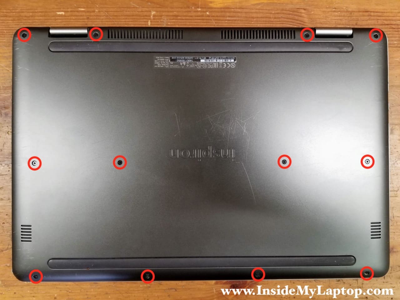
Base cover and battery removal
STEP 1.
Remove twelve screws from the base cover.
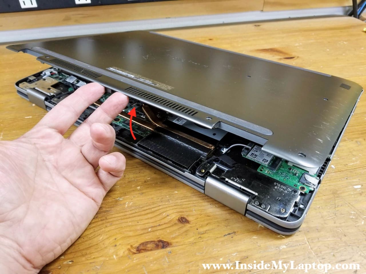
STEP 2.
Remove the base cover. Start lifting up the cover from the display hinge area.
STEP 3.
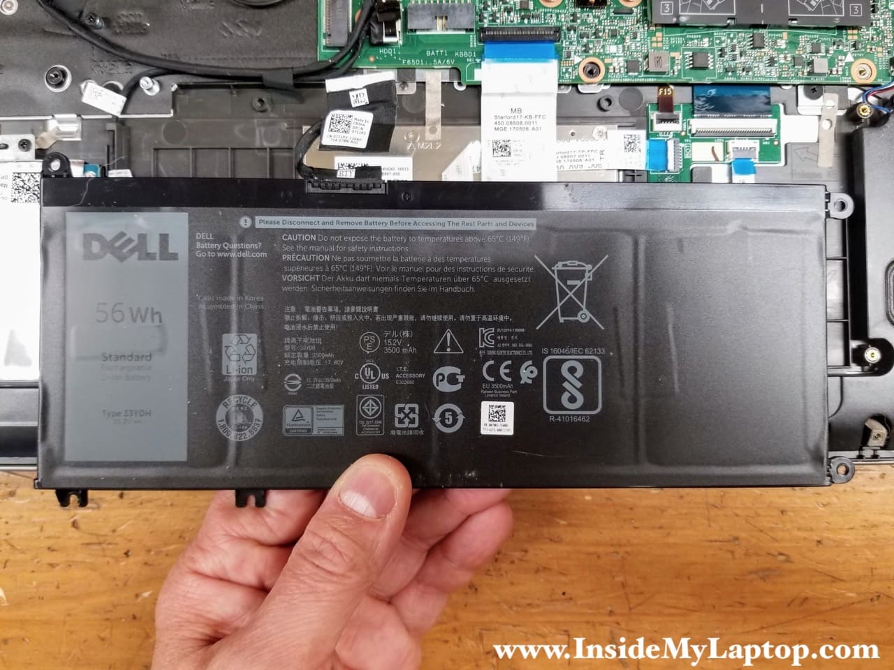
Remove four screws attaching the battery to the top case. Disconnect the battery cable.
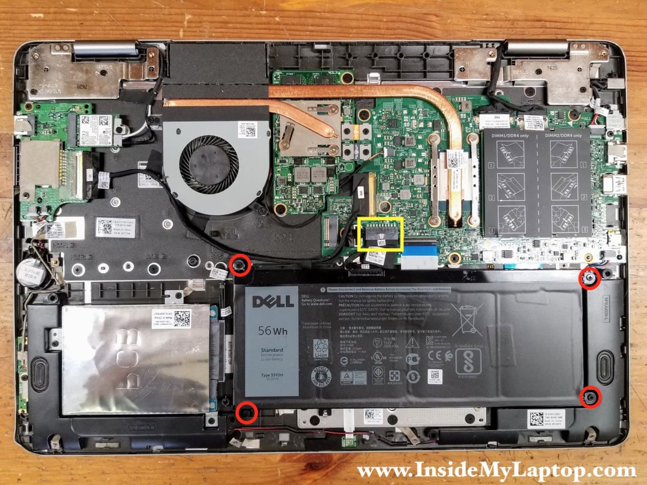
STEP 4.
Remove the battery.
Dell Inspiron 17 7778 7779 battery type: 33YDH.
Hard drive and memory removal
STEP 5.
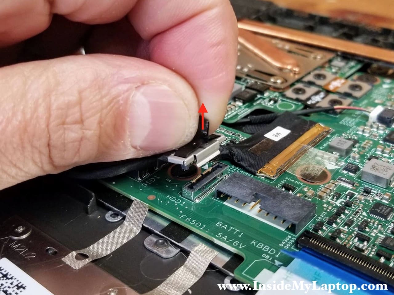
Remove three screws from the 2.5″ hard drive bracket. Disconnect the hard drive cable from the motherboard.
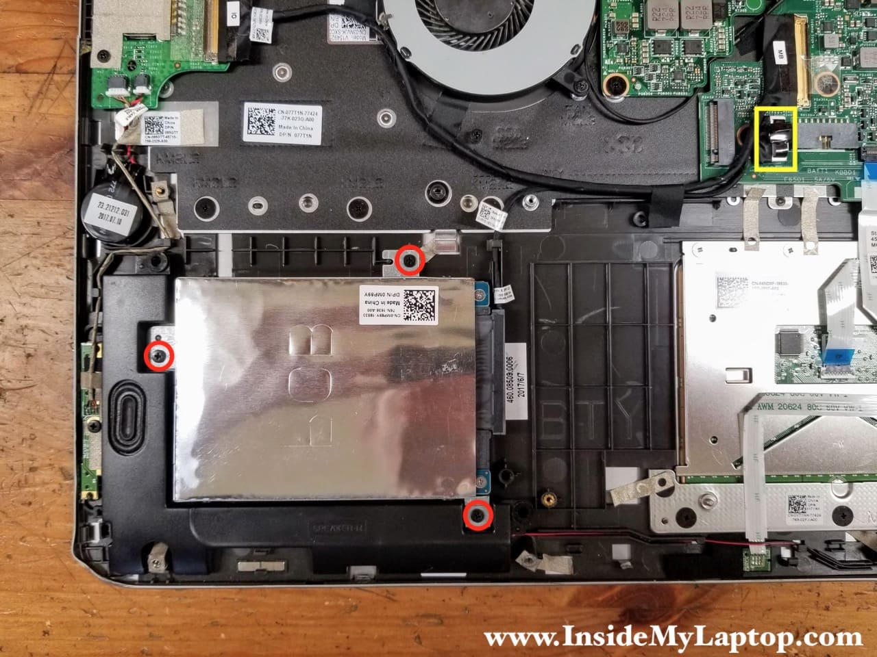
There is a black tab on the top of the connector. Pull the hard drive cable connector up to unplug it from the motherboard.
STEP 6.
Remove the 2.5″ hard drive with the SATA cable attached to it. You can upgrade this laptop with a 2.5″ solid state drive to speed up the system.

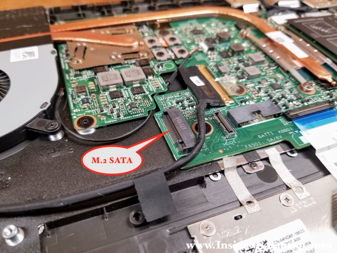
Dell Inspiron 17 7778 7779 2-in-1 has a slot for M.2 SATA SSD (not NVMe). You can mount a type 2280 SSD in there.
STEP 7.
The laptop has two memory slots.
According to Dell specifications Inspiron 17 7778 7779 2-in-1 supports up to 16GB (2x8GB) DDR4 RAM. Some users reported that RAM can be upgrade to 32GB.
Fan, DC jack and Wi-Fi card removal
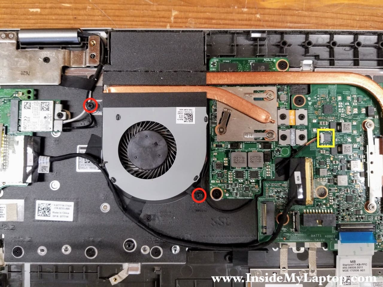
STEP 8.
Remove two screws from the cooling fan and disconnect the fan cable.
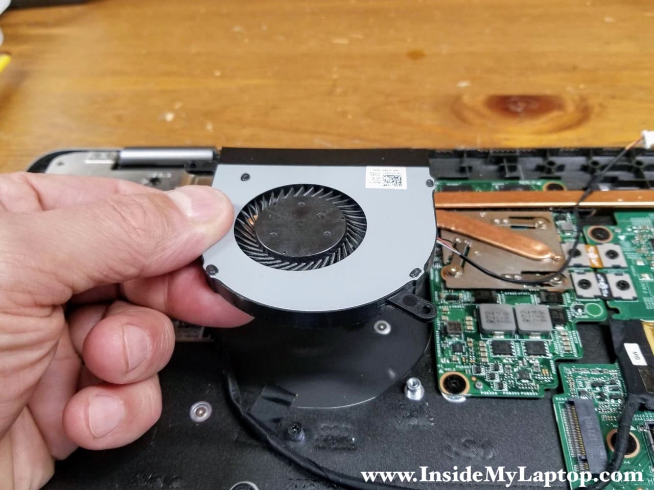
STEP 9.
Lift up and remove the fan.
STEP 10.
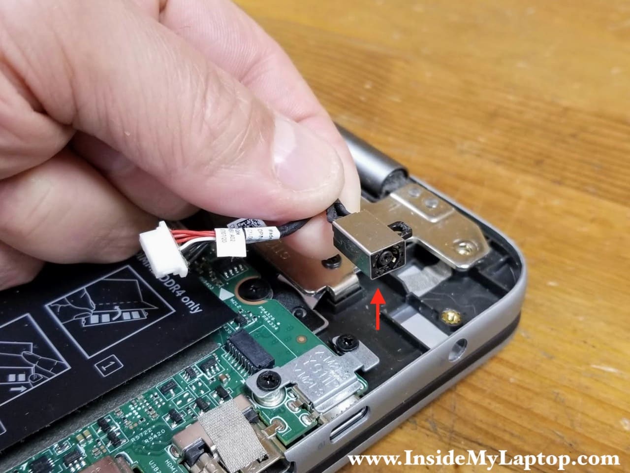
Remove one screws securing the DC power jack. Disconnect the DC jack cable from the motherboard.
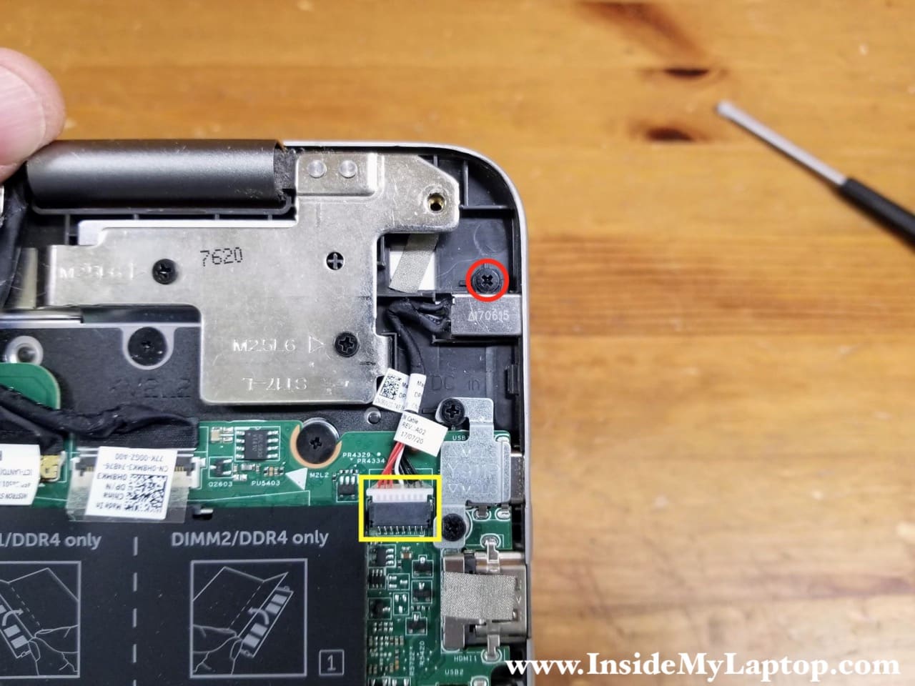
STEP 11.
Remove the DC power jack.
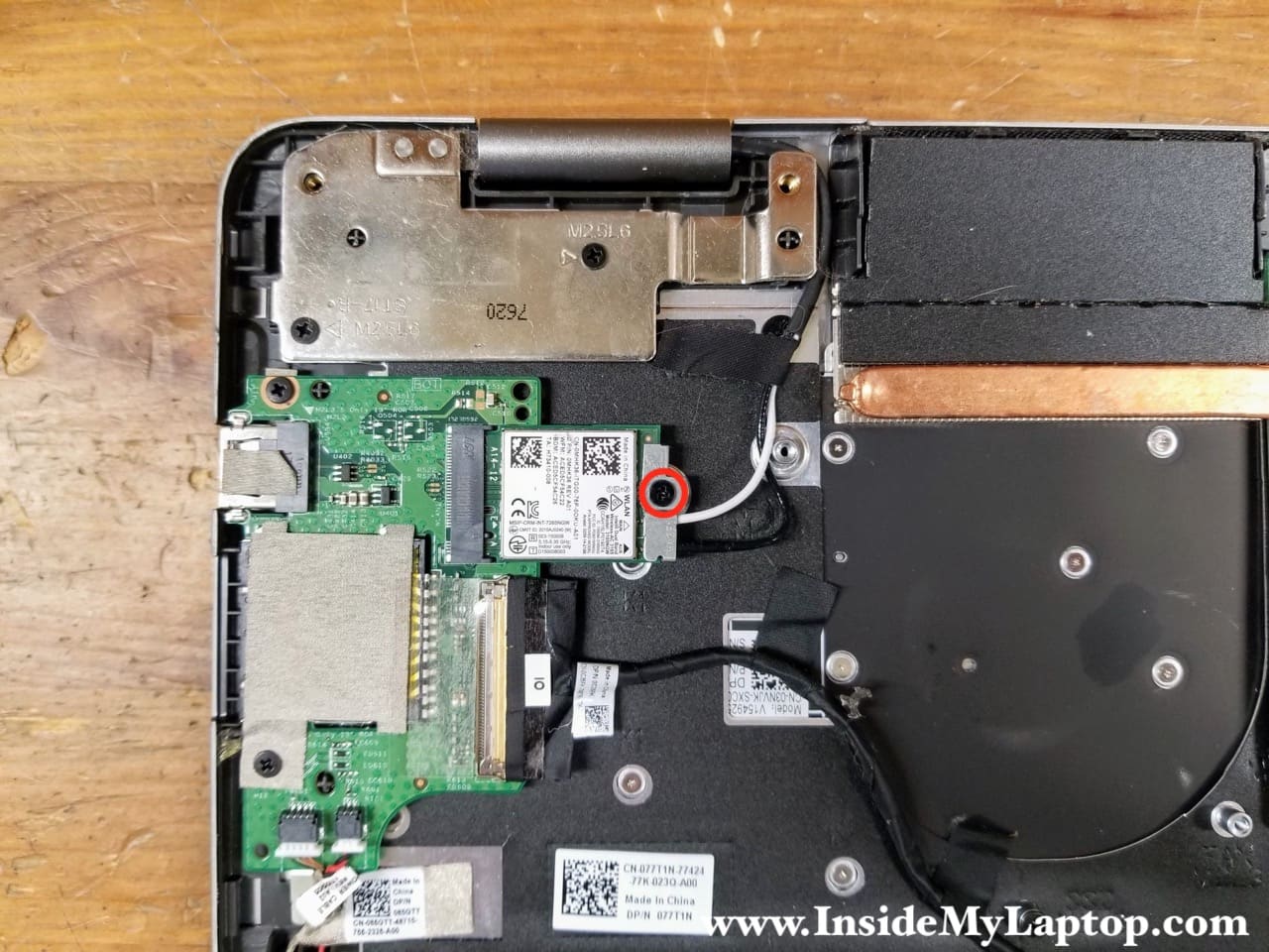
STEP 12.
Remove one screw from the Wi-Fi card mounting bracket. Remove the bracket.
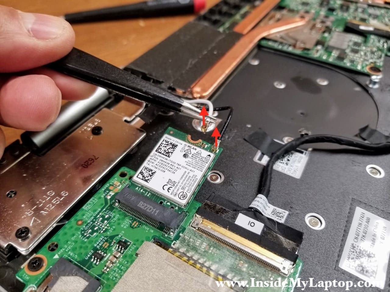
STEP 13.
Disconnect two antenna cables from the Wi-Fi card.
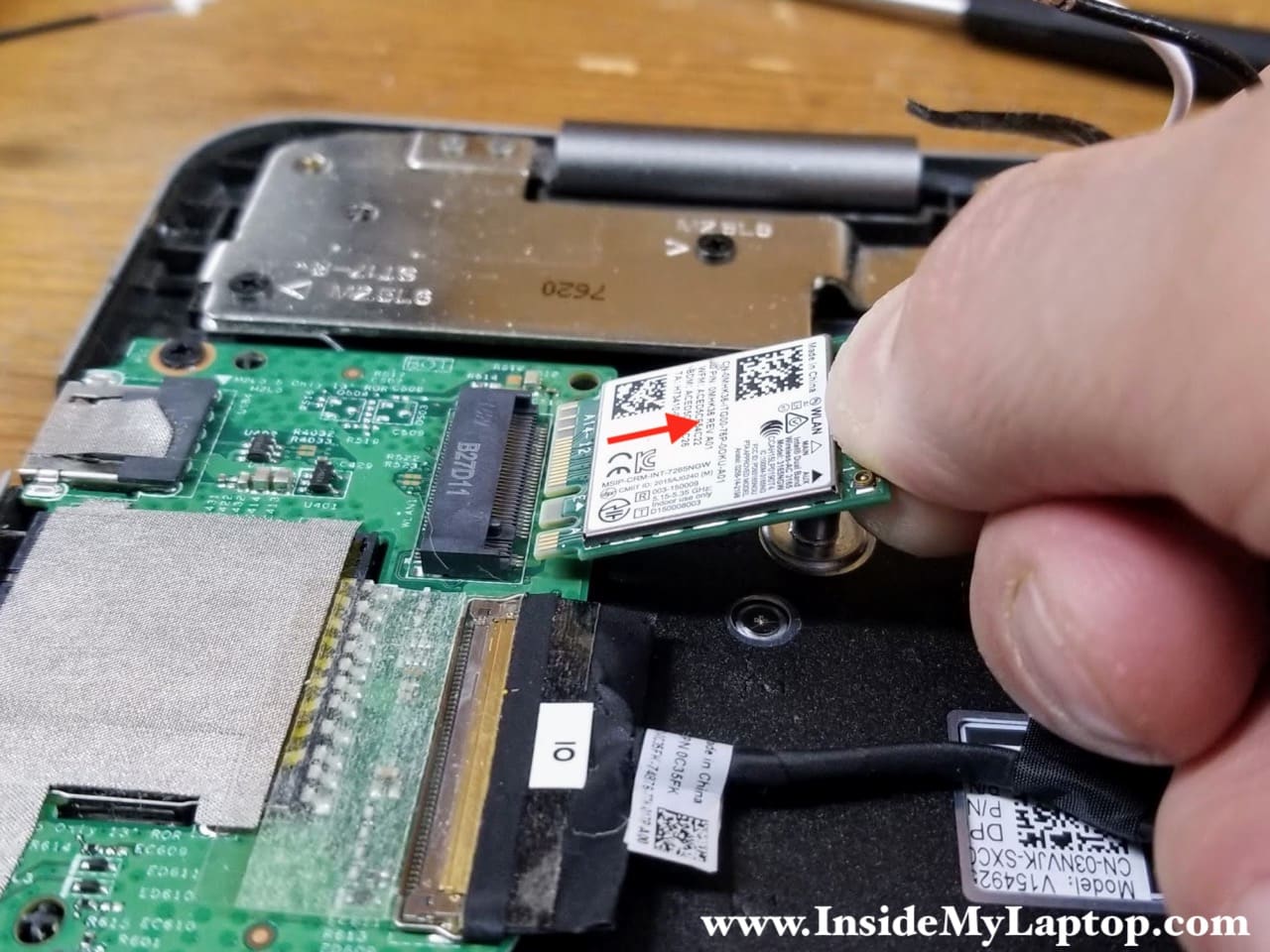
STEP 14.
Remove the Wi-Fi card.
Display panel removal
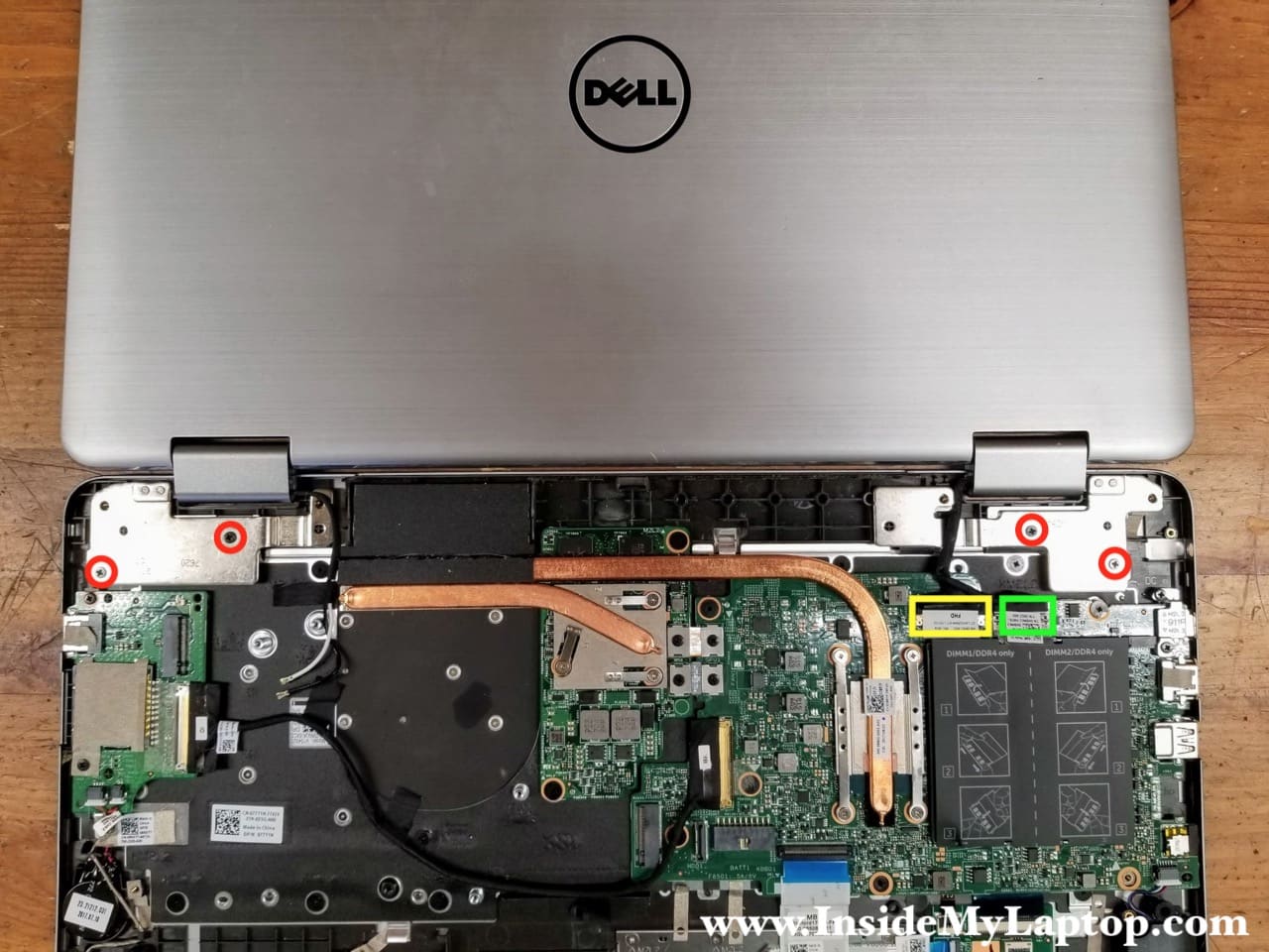
STEP 15.
Open the display panel 180 degrees and place it on the desk as shown on the following picture.
Remove four screws securing the display panel. Disconnect the display cable (yellow) and the touchscreen cable (green).
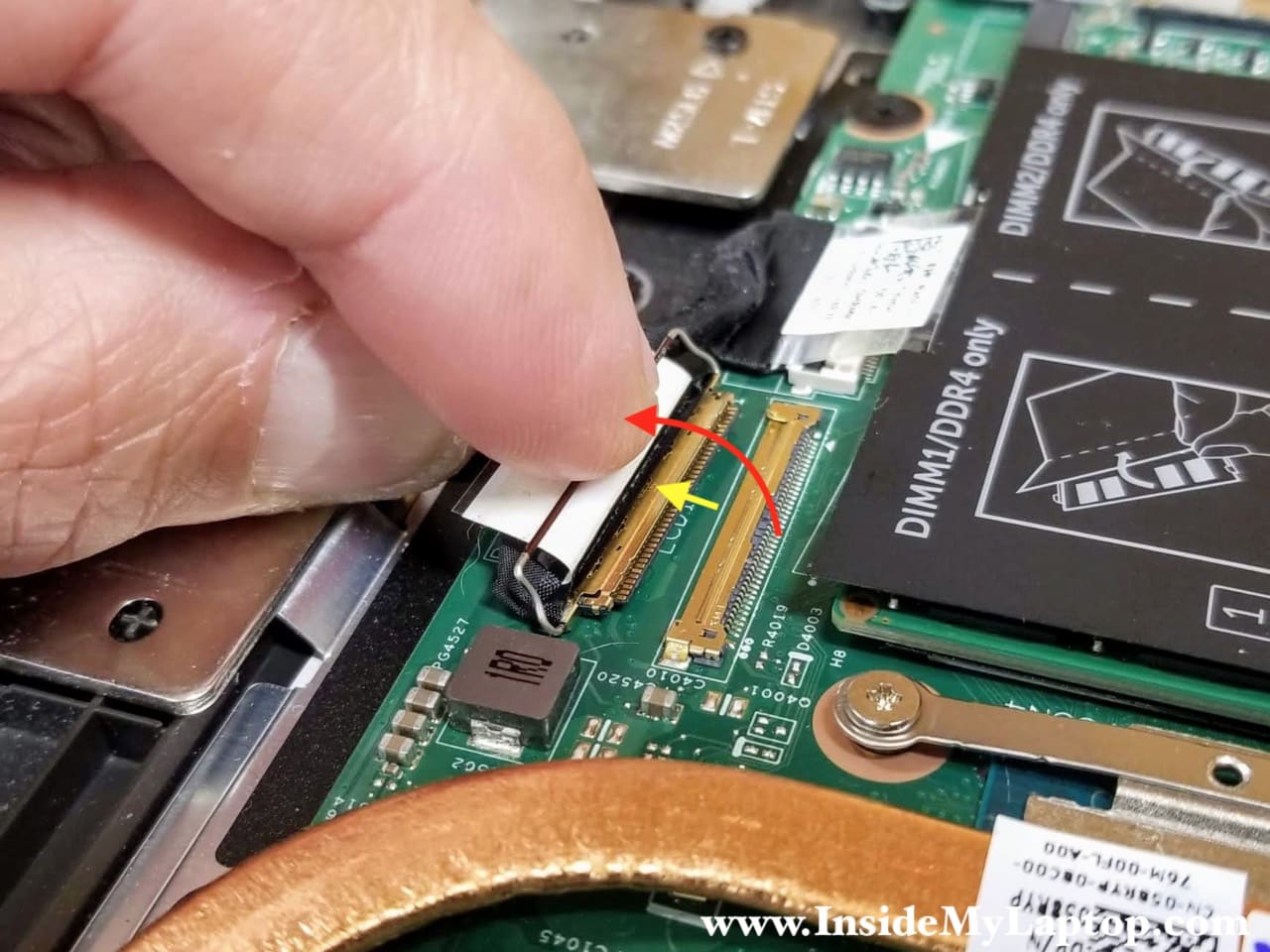
Here’s how to disconnect the display cable. Lift up the metal bracket to unlock the connector. Pull the cable out.
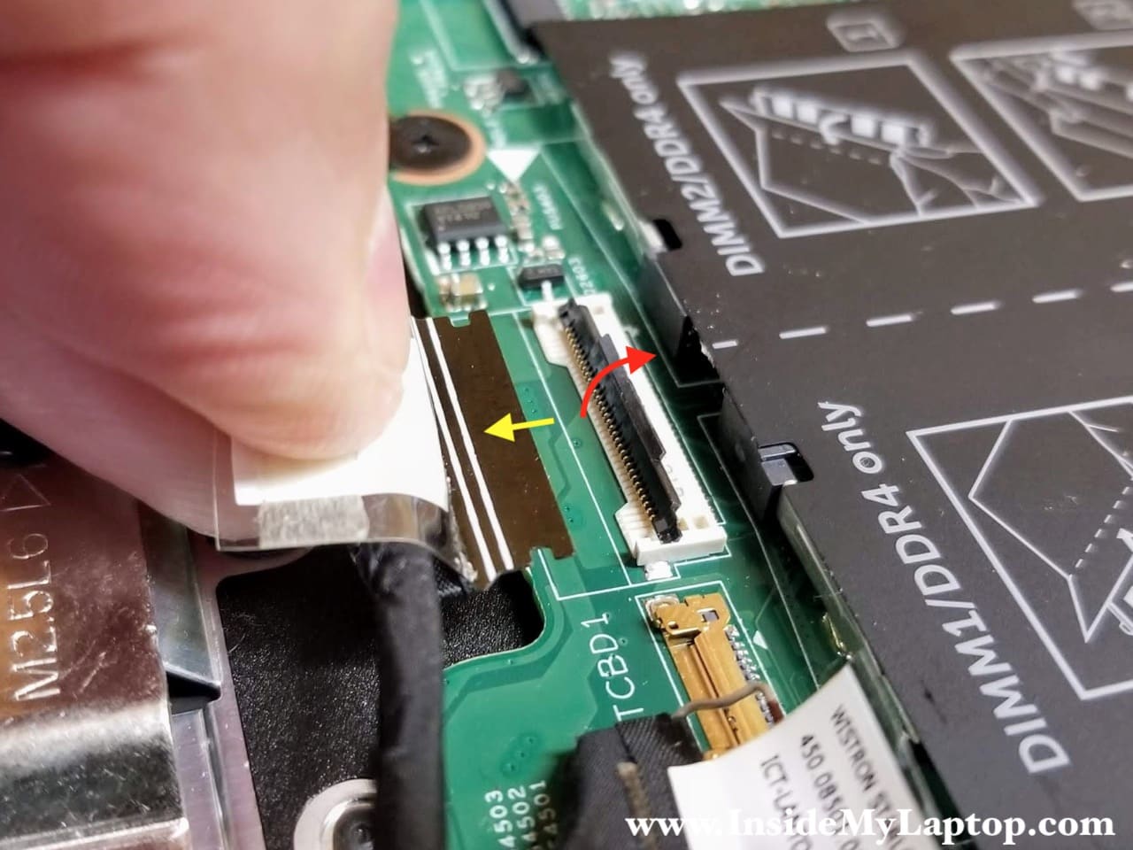
Here’s how to disconnect the touchscreen cable. Lift up the locking tab to unlock the connector. Lift up and remove the cable.
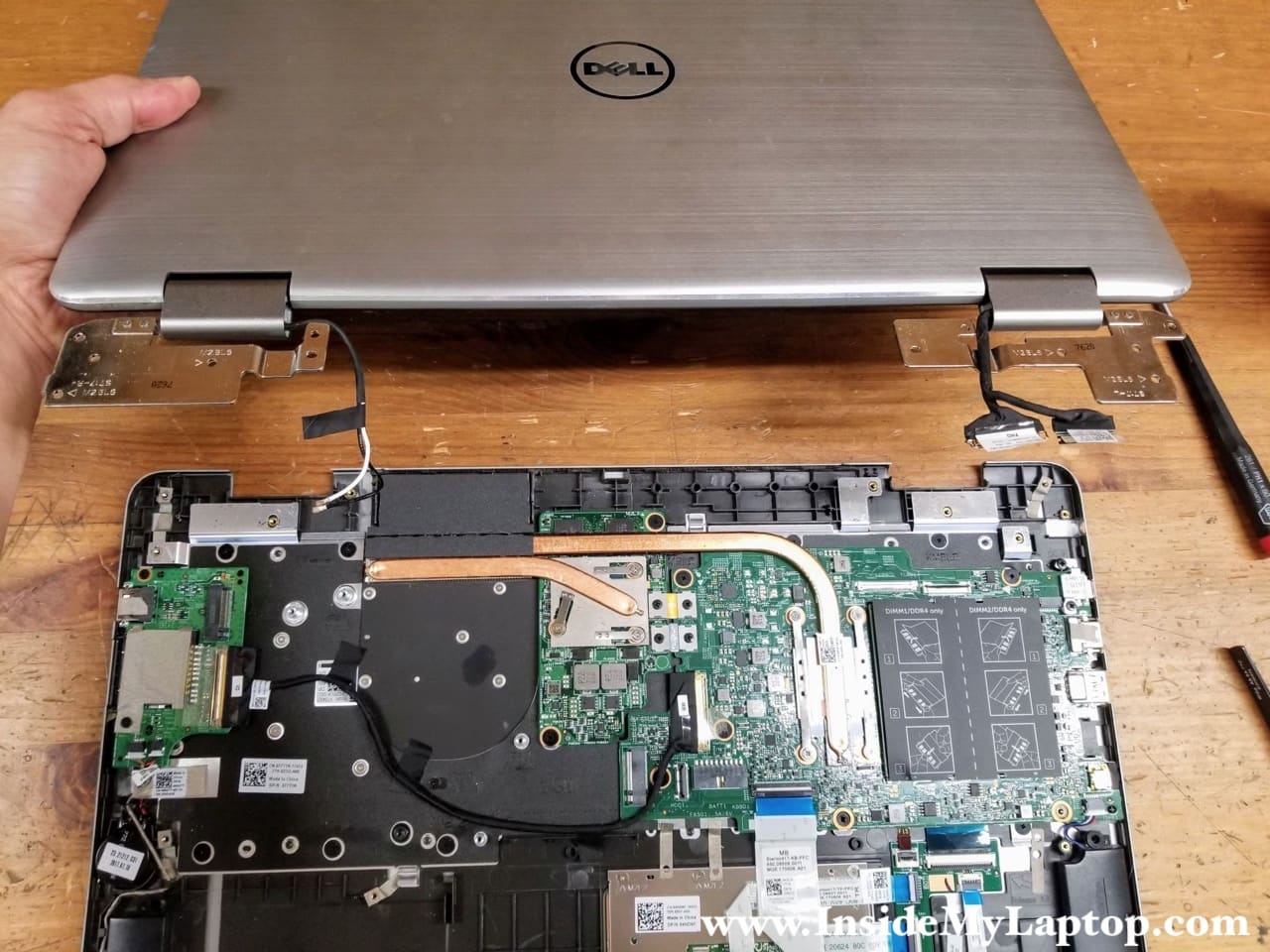
STEP 16.
Remove the display panel from the top case assembly.
Motherboard removal
STEP 17.
Remove all screws securing the motherboard and the GPU (video card) to the top case.
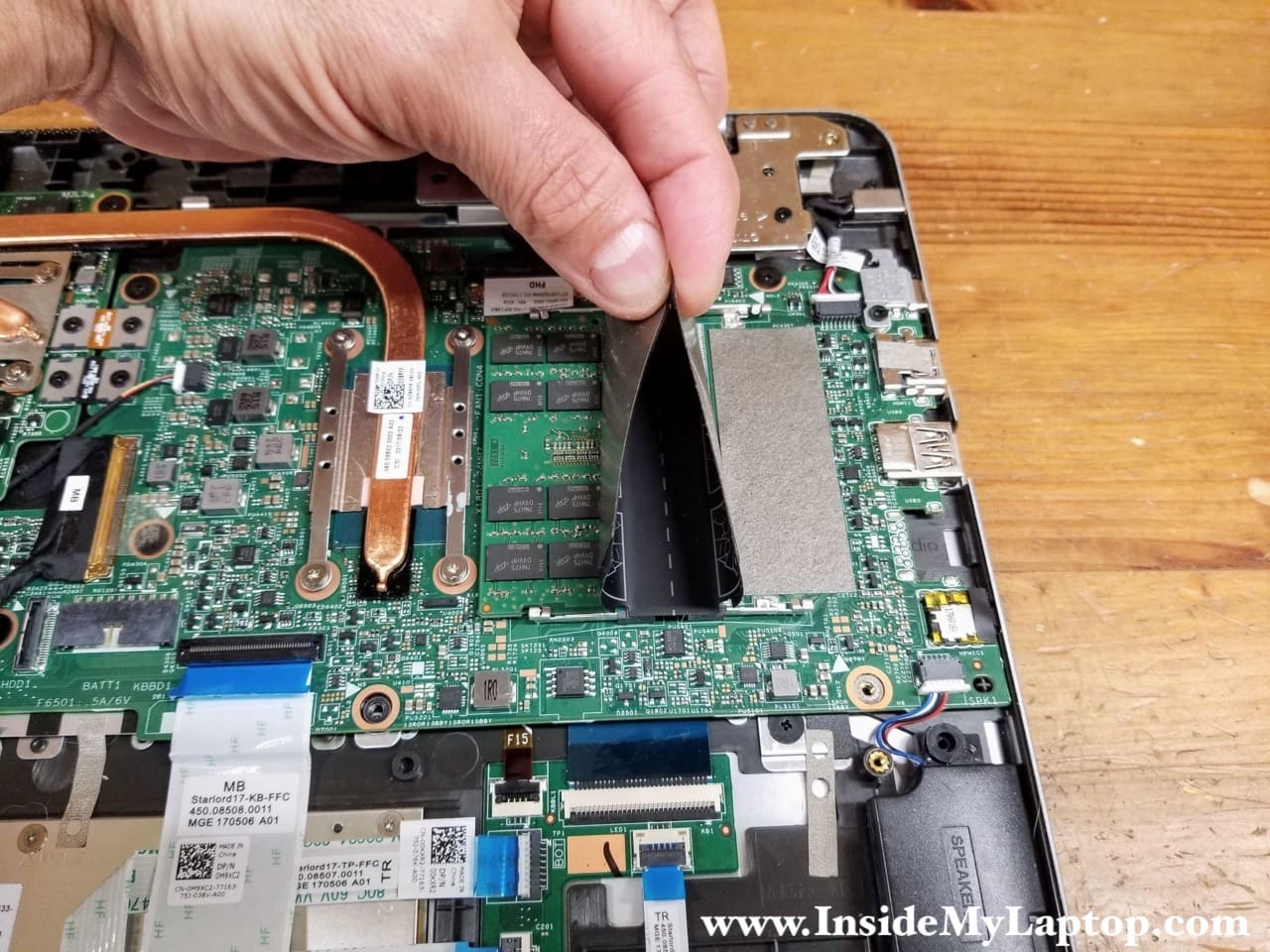
Disconnect the following color-coded cable:
– I/O board cable (yellow).
– Keyboard connector board cable (green).
– Speaker cable (orange).
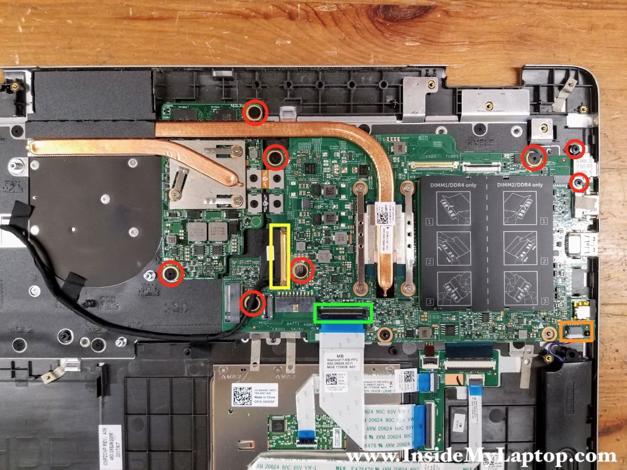
STEP 18.
Remove the USB-C bracket.

STEP 19.
Separate the motherboard from the top case and remove it.
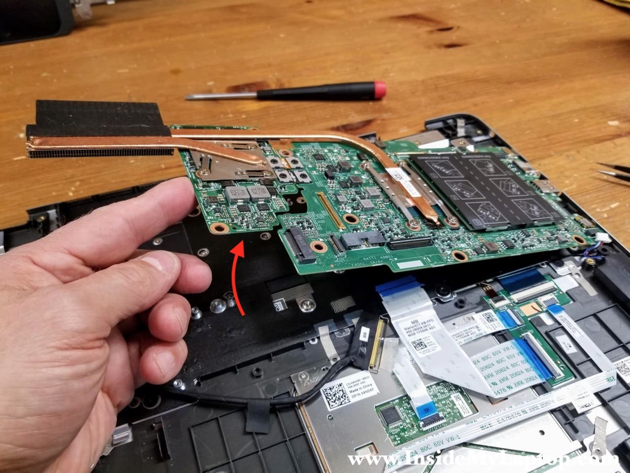
Dell Inspiron 17 7778 7779 motherboard has a removable GPU (video card). In order to separate the GPU from the motherboard it is necessary to remove the heatsink and two brackets connecting the GPU to the motherboard.

Here’s the other side of the motherboard.

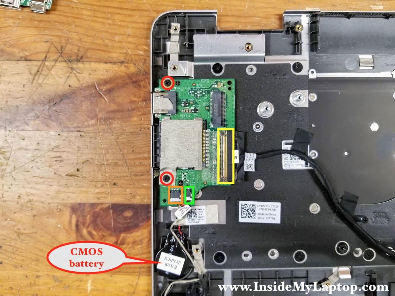
STEP 20.
Remove two screws securing the I/O board. Disconnect the I/O board cable (yellow), power button cable (orange), CMOS battery (green). Remove the I/O board.
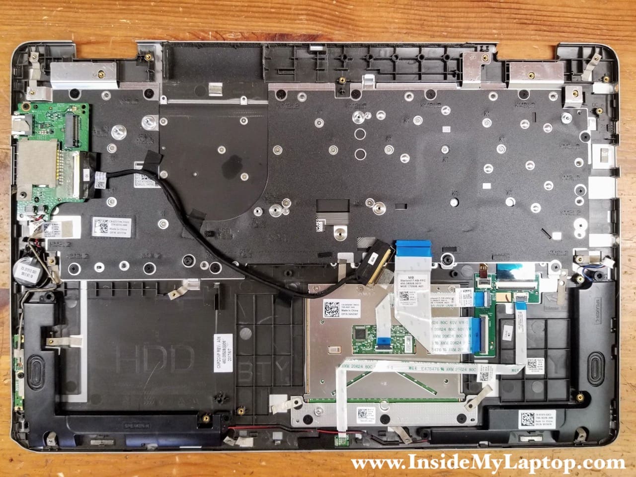
The touchpad can be removed too.

Here’s the top case assembly with the motherboard removed.
Dell Inspiron 17 7778 7779 has a removable keyboard. There are eighteen screws attaching the keyboard to the top case.
Bill Laverty
The letter R has stopped working on my P30E Inspiron andiI am attempting to buy a replacement retainer key and clip but the model is not listed. any idea why that would be
IML Tech
Are you sure that your problem is related to the retainer key and clip? If the key moves properly but doesn’t type, it’s likely you have a problem with the keyboard itself.
regular_user
can we put different keyboard chassis on here will it mess up the format of other parts?
IML Tech
You should use only parts designed for this particular model.