
 Data Structure
 Networking
 RDBMS
RDBMS Operating System
 Java
Java MS Excel
 iOS
iOS HTML
HTML CSS
CSS Android
 Python
 C Programming
 C++
C++ C#
C# MongoDB
 MySQL
MySQL Javascript
 PHP
PHP Physics
 Chemistry
 Biology
 Mathematics
 English
 Economics
 Psychology
 Social Studies
 Fashion Studies
 Legal Studies
- Selected Reading
- UPSC IAS Exams Notes
- Developer's Best Practices
- Questions and Answers
- Effective Resume Writing
- HR Interview Questions
- Computer Glossary
- Who is Who
Description of 8255 PPI
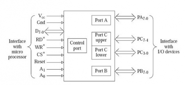
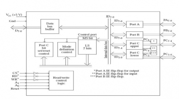
Intel 8255 is a peripheral interface (PPI) chip which is programmable. It is used for the connection of peripheral devices and interfacing. We call Peripheral device also as Input Output device. We use Input Output ports for the connection of Input Output devices. Hence 8255 is a programmable Input Output port chip. It is a 40 pin chip available for dual line packaging. Power supply of +5 Volt DC is needed for its working. It consists of two programmable Input Output ports having of size 8 bits and two programmable Input Output ports of size 4 bits. We call them as Port A, Port B, Port C upper, and Port C lower, respectively. These pins source 1 mA of current at 1.5V, when they are programmed to work as the Output pins.
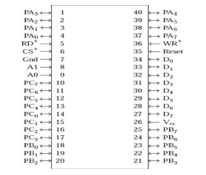
The pin diagram of 8255 is shown below −
We address Port C Upper and Port C lower such that they constitute a port of 8 bit uniquely. Hence we divide port C into 2 parts having 4 bits. Hence we program Port C lower as Input and Port C upper as Output.
The port selection logic is given where the output is set by us to the logic 1 and we reset it to logic 0.
There are three modes of operation performed by 8255 they are as mode 0, mode 1 and mode 2. We call the mode 0 as the simple Input Output or the basic Input Output for performing the simplest mode of operation. Every ports of 8255 can be programmed to work in mode 0. We call mode 1 as the strobed Input Output or handshake Input Output. It is useful when data is supplied to the input device by the microprocessor at irregular interval of time. Finally, when the data is read by the processor the port informs the Input device that the processors already read the data.
The following table depicts the how the port selection is being done in 8255.
| A1 | A0 | Port Selected |
|---|---|---|
| 0 | 0 | Port A |
| 0 | 1 | Port B |
| 1 | 0 | Port C |
| 1 | 1 | Control Port |
Also any line of Port C, which is programmed as output can be set to logic 1, or reset to logic 0 using the single bit set/reset feature of Port C also. This feature reduces software requirement in control-based applications. This facility is provided only for Port C. This feature is also used for enabling/disabling interrupts from 8255 ports.
In the following table, we shall discuss about the Interface of 8255 with Microprocessor − The pins of 8255 that are used for interfacing with a microprocessor are described in the following −
| CS* | It is an active low input pin for 8255. If this pin is at logic 0, the 8255 chip is selected for communication with the microprocessor. If the chip is not selected the data lines D7-0 of 8255 will be in tristate. |
| D7-0 | These pins are the data pins, which are used by 8255 for communication with the microprocessor. They are connected to the data bus of the microcomputer system. |
| RD* | It is an active low input pin for 8255. It is connected to RD* output of 8085. The 8085 activates the RD* input of 8255 when it wants to read the data present in a port of 8255. |
| WR* | It is an active low input pin for 8255. It is connected to WR* output of 8085. The 8085 activates the WR* input of 8255 when it wants to write data to a port of 8255. |
| A1, A0 | These are address-input pins. They select one of the ports inside 8255 for communication with the microprocessor. |
| Reset | It is an active high input pin. It is connected to ResetOut output of 8085. It is used to reset the 8255. After a reset of 8255, all the three ports of 8255 work as input ports in mode 0, which is the simplest mode of operation. Operational modes of Ports are described later. |
In the following table, we shall discuss about the Interface of 8255 with I/O devices −
The pins of 8255 that are used for interfacing with I/O devices are described in the following.
| PA7-0 | These eight pins are used by the 8255 for communicating with an I/O device. These pins are output pins if Port A is programmed as an output port. They are input pins if Port A is programmed for input operation. |
| PB7-0 | These eight pins are used by the 8255 for communicating with an I/O device. These pins are output pins if Port B is programmed as an output port. They are input pins if Port B is programmed for input operation. |
| PC7-4 | These four pins are used by the 8255 for communicating with an I/O device. These pins are output pins if Port C upper is programmed as an output port. They are input pins if Port C upper is programmed for input operation. |
| PC3-0 | These four pins are used by the 8255 for communicating with an I/O device. These pins are output pins if Port C lower is programmed as an output port. They are input pins if Port C lower is programmed for input operation. |

5K+ Views

To Continue Learning Please Login